You can label the crossing pipe locations in profile views and section views.
Labeling crossing pipe locations may result in having two labels on a pipe (one regular pipe label and one crossing pipe label). If this is not desirable, you can use the Null label styles that are provided in the Autodesk Civil 3D templates. Null label styles are set as the default styles for crossing pipe labels.
To label the locations in profile view where pipe network pipes cross an alignment
- Design the pipe network and add it to a profile view. Tip: You can add the pipe network to the profile view when creating a profile view or you can use the Draw Parts in Profile command to add the parts to an existing profile view.
- Edit the pipe style so that the crossing pipe components are visible in profile view. On the Display tab in the Pipe Style dialog box, select Profile as the View Direction and then ensure that the crossing pipe components that you want to display are set to be visible.
- Set up a Crossing Profile label style for pipes. A labels collection is available for these label styles in Toolspace. On the Settings tab, expand Pipe
 Labels Crossing Profile and use the context menu to create or edit a label style. Several crossing pipe properties are provided in the Text Component Editor which you can use to label the crossing pipe chainage and level information.
 - Select the pipe network to display the Pipe Network contextual ribbon.
- Click Labels & Tables panel Add Labels, and then select either Entire Network Profile or Single Part Profile. You can drag the label off the pipe as needed as shown in the following illustration.
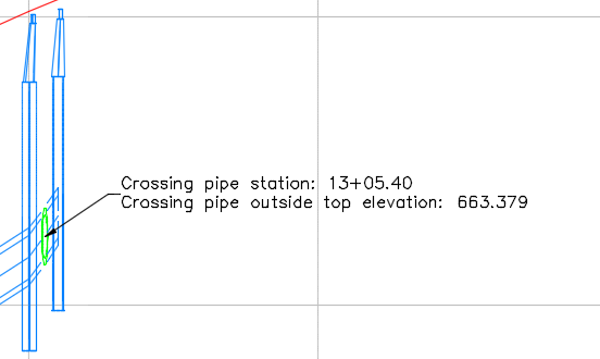
If the crossing pipe is moved to a different chainage along the alignment, the labels will be updated with the new chainage and level information.
To label the locations in section view where pipe network pipes cross a sample line
- Design the pipe network and add it to section views. Tip: You can add the pipe network to the section views when creating section views or by editing the properties of an existing section view or section view group.
- Edit the pipe style so that the pipe components are visible in section view. On the Display tab in the Pipe Style dialog box, select Section as the View Direction and then ensure that the pipe components that you want to display are set to be visible.
- Set up a Crossing Section label style for pipes. A labels collection is available for these label styles in Toolspace. On the Settings tab, expand Pipe Labels Crossing Section and use the context menu to create or edit a label style. Several properties are provided in the Text Component Editor which you can use to label the pipe section level information.
- Select the pipe network to display the Pipe Network contextual ribbon.
- Click Labels & Tables panel Add Labels, and then select either Entire Network Section or Single Part Section. You can drag the label off the pipe as needed as shown in the following illustration.
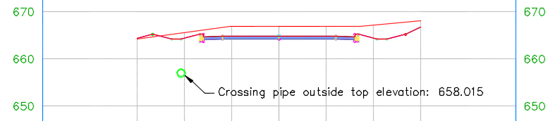
If the crossing pipe is moved to a different level, the labels will be updated with the new information.