Applies a texture-baked Normals map to a material.
This map is typically assigned to the Bump or Displacement component of a material, or both at once. Using the map for Displacement can correct edges that look too smooth, however extra faces are added to the geometry. For more information on Normals maps, see Baked Texture Elements.
-

 Material Editor > Material/Map Browser > Maps > General > Normal Bump
When you save a rendered file to be used as a Normal Bump map, make sure to click Data Image. The values in Normal Bump maps do not represent colors and should not be color-managed.
Interface
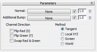
- Normal
- Typically contains a Normals map generated by
Render To Texture.
Use the toggle to enable or disable use of the map (default=on). Use the spinner to increase or decrease the map's effect.
- Additional Bump
- This optional component can contain an additional map to modify the bump or displacement effect. It is treated as a regular
Bump map.
Use the toggle to enable or disable use of the map (default=on). Use the spinner to increase or decrease the map's effect.
Channel Direction group
By default, the Normals map's red channel indicates left (larger values) versus right (smaller values), while green indicates down (larger values) versus up (smaller values), and blue indicates vertical distance. The controls in this group let you adjust that interpretation.
 General panel.
- Flip Red (X)
- Flips the red channel so that left and right are reversed.
- Flip Green (Y)
- Flips the green channel so that up and down are reversed.
- Swap Red & Green
- Swaps the red and green channels to rotate the normals.
For example, if the normal is (228,178, 255), the normal points in the direction of 2 o’clock. Swapping Red and Green results in a normal of (178, 228, 255), which points in the direction of 1 o’clock.
Method group
The Method group lets you choose which coordinate to use on the normals. These controls are the same as those in the Projection Options dialog.
-
Tangent (The default.) Project at a tangent to the target object's surface.
This is the method to use for objects that both move and deform, such as animated characters.
-
Local XYZ Project using the object's local coordinates.
This method can be used for stationary or moving objects, but not for objects that deform: If the object deforms, the projection will appear incorrect at some frames.
-
Screen Project using screen coordinates; that is, flat projection in the Z axis. X is horizontal, increasing in a positive direction to the right; Y is vertical,increasing in a positive direction upward; and Z is perpendicular to the screen, increasing in a positive direction toward the viewer.
This method is useful mainly for stationary objects seen only from a single angle; for example, a statue seen through a window.
-
World Project using world coordinates.
This is useful mainly for objects that don't move or deform; otherwise, a moving object with world-projected normals will appear to “swim” through the texture.