In this exercise, you will create an outer surface boundary from a polyline.

This exercise continues from Exercise 3: Adding Breaklines to a Surface.
Create an outer boundary from a polyline
- Click Home tab
 Layers panel
  Layer drop-down. Next to the _EG-BNDY layer, click
  . Click in the drawing to exit the Layer Control list.
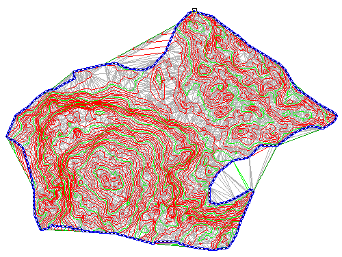
 A blue polyline, which represents the extents of the site, is displayed. This polyline was imported with the original surface contours.
- In Toolspace, on the Prospector tab, expand the
 Surfaces
 EG
EG
 Definition collections. Right-click
  Boundaries. Click .
 - In the Add Boundaries dialog box, specify the following parameters:
- Name: EG - Outer
- Type: Outer
- Non-Destructive Breakline: Cleared
- Mid-Ordinate Distance: 1.000
- Click OK.
- Select the blue polyline.

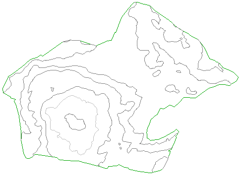
The boundary is added to the surface definition, and the surface display in the drawing is clipped to the area that is defined by the new outer boundary.
This exercise uses Surface-1B.dwg with the modifications you made in the previous exercise.
Hide the polyline and change the surface style
- Click Home tab
 Layers panel
  Layer drop-down. Next to the _EG-BNDY layer, click
  .
. - Select the surface. Right-click. Click Surface Properties.
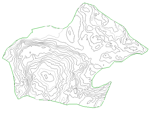
- In the Surface Properties dialog box, on the Information tab, for Surface Style, select Contours 5' and 25' (Background). Click OK.
In the selected surface style, contours are displayed in muted colors at broad intervals. This display allows the major surface features to remain visible while you focus on other aspects of the site design.

To continue to the next tutorial, go to Working with Large Surfaces.