This tutorial demonstrates how to create a TIN surface, and then add contour, breakline, and boundary data to the surface.
When you create a surface, its name is displayed in the Surfaces collection in Toolspace on the Prospector tab. From this location, you can perform other operations, such as adding data and editing the surface. When first created, the surface is empty, so it is not visible in the drawing.
After data has been added to a surface, it becomes visible in the drawing in accordance with the display settings specified in the referenced surface style.
TIN Surfaces
A TIN surface is composed of the triangles that form a triangulated irregular network. A TIN line is one of the lines that makes up the surface triangulation.
To create TIN lines, Autodesk Civil 3D connects the surface points that are closest together. The TIN lines form triangles. The elevation of any point in the surface is defined by interpolating the elevations of the vertices of the triangles that the point lies in.
TIN surface with contour lines displayed

Contour Data
Contours are graphical illustrations of surface elevation changes. You can create a surface from contours drawn as 2D or 3D polylines that have x, y, and z coordinate data.
Boundaries
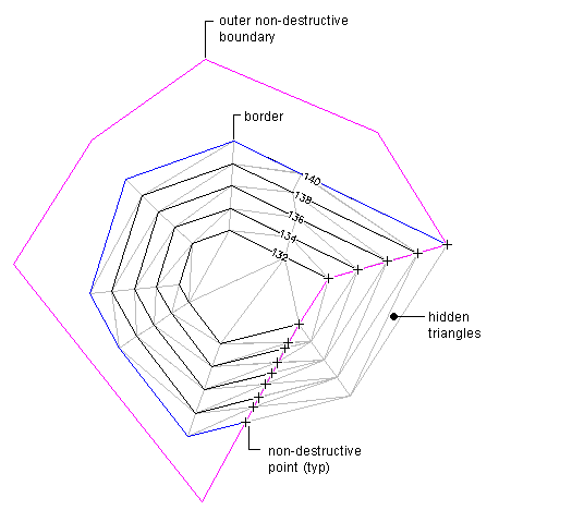
Boundaries are closed polylines that affect the visibility of the triangles either inside or outside the polylines. An outer boundary defines the extents of the surface. All triangles inside the boundary are visible, and all triangles that are outside the boundary are invisible.
Areas hidden by boundaries are not included in calculations, such as total area and volume.
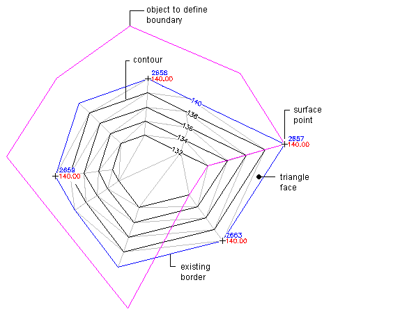
Surface boundaries are defined by selecting existing polygons in the drawing. The surface definition displays the numerical ID and a list of vertices for each boundary.
A surface before adding a non-destructive outer boundary

The effects of a non-destructive outer boundary

Breaklines
Breaklines define linear surface features, such as retaining walls, curbs, tops of ridges, and streams. Breaklines force surface triangulation to run along the breakline; triangles do not cross a breakline.
Breaklines are critical to creating an accurate surface model. Breaklines are important because it is the interpolation of the data, not just the data itself, that determines the shape of the model.
You can use 3D lines or 3D polylines as breaklines. Each vertex on the polyline is converted to a TIN point with the same XYZ coordinates. For 3D lines, each line that you select is defined as a two-point breakline.