- Click Home tab
 Create Design panel
  Alignment drop-down
  Create Connected Alignment
Find.
- In the drawing, select the first alignment to connect.
- Select the second alignment to connect.
- Select the location for the connected alignment.
Temporary graphics are displayed in the drawing.

- Select a different location or press Enter to accept the current location and to display the Create Connected Alignment dialog box.
- Click the
Parameters tab to specify parameters for the connected alignment. A few unique options for connected alignments are as follows:
-
Curve Group Type: Use this option to select the type of curve group to create.
- Circular Fillet
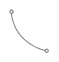
- Spiral-Curve-Spiral
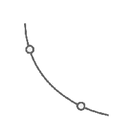
- Reverse Spiral-Spiral-Curve-Spiral

- Reverse Spiral-Curve-Spiral-Spiral
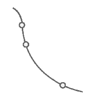
- Reverse Spiral-Spiral-Curve-Spiral-Spiral
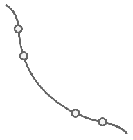
- Three Centered Arc
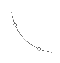
- Circular Fillet
- Curve Radius: Use this option to change the default radius for the connected alignment for all curve group types except for three centered arc.
Note: If you want to change the curve radius after the alignment is created, you can grip edit the alignment using the radius grip, or you can change the radius on the Connection Parameters tab of the Alignment Properties dialog box.
- Arc Parameters/Spiral Parameters: Click the browse button
 to access settings for the arcs and spirals in the curve group type.
- Degree of Curvature: Use this option to specify whether the connected alignment should be less than 180 degrees or greater than 180 degrees.
- Offsets: Use these options to specify offsets from the parent alignments.
- Connection Overlaps: Use these options to change the default connection overlaps for the connected alignment.
Note: The connection overlaps must be greater than 0.The following example shows the effect of a 50 foot overlap. The connected alignment is overlapped onto the existing alignments for 50 feet.

If the overlap occurs on a curve, the overlapping portion of the connected alignment will follow the curve.
 Note: If you want to change the connection overlap values after the alignment is created, you can grip edit the overlap segments.
 - Connected Profile tab options: Use these options to create a profile for the connected alignment between the two existing profiles that you specify.
-
Curve Group Type: Use this option to select the type of curve group to create.
- Click
OK to create the connected alignment and optional profile.
Note: The alignment is created as a curb return alignment. You can change this on the Information tab of the Alignment Properties dialog box if needed.
- If you chose to create a connected profile, create a profile view for it in the drawing.