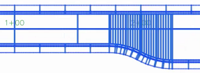
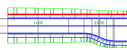
Using multiple dynamic baselines in a corridor, rather than using a single centerline baseline, provides you with independent control over the individual corridor components as well as overall control due to the dynamic relationship between corridor components.
Some of the benefits of using multiple dynamic baselines when creating corridors are as follows:
- Independent control over each baseline.
- Each baseline can have its own assembly that is relevant to just that baseline. For example, rather than designing a complex assembly that will be applied at the centerline out to form the entire corridor, which might need lanes, curbs and gutters, sidewalks, daylighting, and other conditions, you can design a simpler assembly for each baseline. For example, an assembly containing only a curb and gutter could be applied along an offset baseline, or a daylighting assembly could be applied to a sidewalk baseline.
- You can specify different assembly frequencies for each baseline.

- Sections remain radial to the geometry that you are using as a baseline, so if the horizontal geometry of the baseline is different from the centerline, the sections will be created with respect to the baseline geometry.

- Overall control due to the ability to use dynamic baseline components.
- If you make a change to the centerline alignment or profile, the corridor components that are related to that horizontal and vertical geometry are updated.
- The geometry of extracted dynamic feature lines will stay relative to other parts of the corridor such as its component alignments and profiles.
Examples of dynamic baselines
Examples of dynamic baselines that you can use in corridors are as follows:
- Offset alignments and profiles: Create dynamic offset alignments and associated profiles by using the
Create Offset Alignment command.
When you use these offsets as additional baselines in the corridor, the offsets remain relative when the centerline alignment or profile is updated. You can then assign a curb and gutter assembly to the offset alignment, for example. By using dynamic offset alignment baselines, the geometry of the offsets, and their generated corridor components, remains relative to the horizontal and vertical geometry of the centerline.
- Connected alignments and profiles: Create dynamic connected alignments and profiles by using the
Create Connected Alignments command.
You can use connected alignments and profiles where roads intersect.
- Extracted feature lines: Extract dynamic feature lines from a corridor and use them as a baseline in the same corridor. By working with dynamic extracted feature lines, the geometry remains relative to the corridor as a whole. For more information, see
About Extracting Corridor Feature Lines from a Corridor and
To Add Baselines to a Corridor.
Note: To prevent a circular dependency from occurring, a dynamic extracted feature line cannot be used to replace the baseline of its parent(s) in the same corridor. For example, if you extract a dynamic feature line that represents a sidewalk, and then use that feature line as a baseline in the corridor and attach a daylighting assembly that creates a daylight line, a dynamic feature line that is then extracted from the daylight line cannot be used to replace the baseline of the sidewalk or the sidewalk's parent. A message is displayed if you try to select a dynamic extracted feature line in this type of situation when editing baselines on the Parameters tab of the Corridor Properties dialog box.
The following corridor was created with a combination of dynamic offset baselines, dynamic connected alignments, and extracted feature lines.

This corridor was created by applying the following assemblies to the baselines.

- A lanes assembly was attached to the centerline baseline to form the pavement area.

- The left and right centerline offsets were added as baselines to which curb/gutter/sidewalk assemblies were attached.

- The left and right sidewalks were extracted as dynamic feature lines and added as baselines to which daylighting assemblies were attached.

- Where the road intersection occurs, the regions of the baselines that control the left curb/gutter/sidewalk and daylighting were split to create gaps where those components are not created.
- Connected alignments and profiles were created at the road intersection and added as baselines to which curb return assemblies were attached.

Moving the centerline will update the offsets, the connected alignments, and the other related corridor components.

