Assign properties to the second shot component elements
In this task you specify the properties necessary to run a two-shot overmolding analysis.
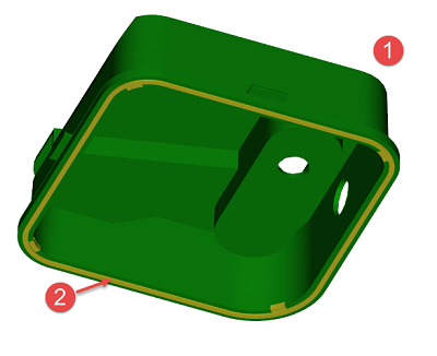
Rotate the model so you can see both parts. The first shot is the one in green (indicated as 1 in the image). And the second shot is yellow (indicated as 2 in the image).
 Tip: Turn on and off the layers to help you identify the 1st and 2nd shot components and their respective runner systems.
Right-click the TankSealTrimmed Tetras layer and select Hide all other layers.
Band select the entire tank seal trimmed tetras (second yellow shot).
Click
 (Mesh tab > Properties panel > Edit).
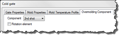
Select the Overmolding Component tab.
Select 2nd shot from the drop-down list and select OK.
In the Layers panel, activate the 2nd Shot runners layer, to make the components visible.
Turn off the TankSealTrimmed Tetras layer, so only the 2nd Shot runners components are visible.
Repeat the steps above to assign all the components of this layer to the 2nd shot, including:
Gate orifice (Cold gate 1 mm)
Cold gate body, tapered section (Cold gate 1 x 5 mm) - edit the entire taper section
Cold runner (Cold runner 5 mm)
Hot gate (Hot gate 2 mm)
Hot gate, tapered section (Hot gate 2 x 6 mm) - edit the entire taper section
Hot sprue (Hot sprue 6)
The 2nd shot elements turn beige, as shown below.
Make all mesh element layers visible.
Click
 (Boundary Conditions tab > Injection Locations panel > Injection Locations), and set the injection location at the start of the first component sprue.
Click
 (Boundary Conditions tab > Injection Locations panel > Overmolding Locations), and set the injection location at the start of the second component sprue.
Click the Next topic link below to move on to the next task of the tutorial.
Parent topic: Two-Shot overmolding
Previous topic: Select the molding process
Next topic: Setup the two-shot overmolding process