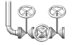
Add valves.
To insert a valve
- On the ribbon, click Home tab
 Part Insertion panel Spec Viewer.
 - In the Spec Sheet, click to select a valve (for example: globe valve).
- In the Pipe Spec Viewer, click Insert in Model.
- If the insertion point is not located at the desired port, press CTRL.
- Hold down SHIFT and right-click in the drawing area. Click an object snap (for example: Midpoint).
- Click to specify a point on the pipe line.

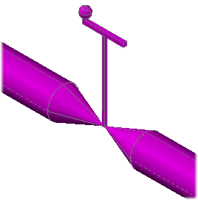
- Click a valve rotation or press ENTER for zero.
- To finish adding valves to the model, press ENTER .
To change a valve operator
- In the drawing area, click to select a valve.
- Right-click in the drawing area. Click Properties.
- In the Properties palette, click Plant 3D Part Properties Valve Operator.
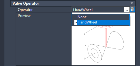
- In the Operator list, click a valve operator (for example: HandWheel).
To override a valve operator
- In the drawing area, click to select a valve.
- Right-click in the drawing area. Click Properties.
- In the Properties palette, click Plant 3D Part Properties Valve Operator.
 In the Operator box, click the valve operator override button.
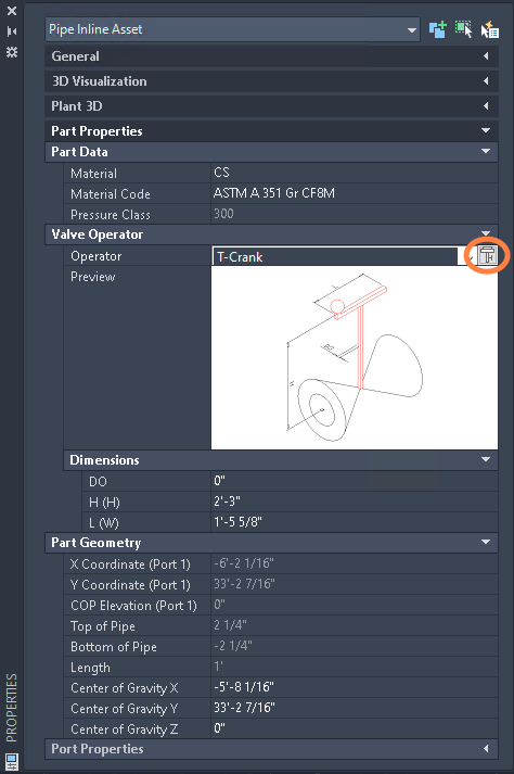
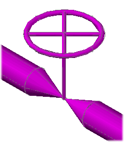
- In the Override Valve Operator dialog box, under Select Operator Shape, click an operator shape (for example: T-Crank).
To place a valve at a precise distance from a fitting
- In the Spec Viewer, in the Spec Sheet, click a valve.
- Click Insert in Model.
- Hold down SHIFT and right-click in the drawing area, click From.
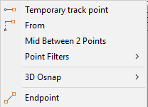
- Hold down SHIFT and right-click in the drawing area. Click Node.
- Click to specify a point on a fitting.
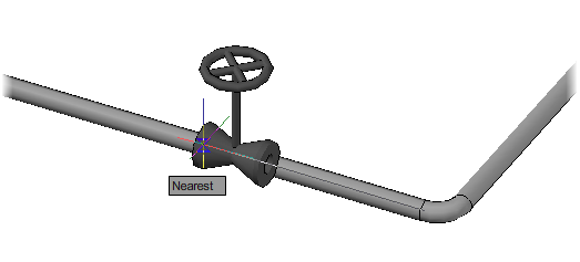
- Hold down SHIFT and right-click in the drawing area. Click Nearest.
- Hover the mouse over the header to display the osnap glyph (do not click).
- If you want to insert at the midpoint of the valve, enter i (Insertionpoint) twice. Note:
When you are tracking over a piping component, attachment port and insertion point options display on the command prompt.
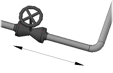
- Enter a distance to place the valve (for example: 48).
If No Endpoint Found for Specified Point displays when using the Near object snap, you can increase aperture size or zoom out. To snap correctly, the Nearest osnap glyph must be visible when the mouse is directly over the pipe centerline.
- Press ENTER to finish adding valves.
Note: This procedure illustrates how to use the from osnap to place components. In most situations, it is easier to use dynamic dimensions.
To create a valve assembly while routing
- At a plantpipeadd prompt, enter i (Insert).
- In the Part Placement dialog box, click the Valves Category icon.

- In the Class Types list, click a component description (for example: Gate Valve).
- In Available Piping Components, click component (for example: Gate Valve, Solid Wedge, 300LB, RF).
- Click Place.
- At the command prompt, enter f (Fitting-to-fitting).

- Click to specify a component rotation or press ENTER for zero (for example: 45).
- At the command prompt, enter i (Insert).
- In the Class Types list, click a component description (for example: Globe Valve).
- In Available Piping Components, click a component (for example: Globe Valve, 300LB, RF).
- Click Place.
- Click to specify a component rotation or press ENTER for zero.
- Repeat steps 8 - 12 for additional fittings (for example: another gate valve).