Use this dialog to define buckling length of members.
Access
- Click the Buckling length coefficient Y or Z button in the Member Definitions - Parameters dialog.
Dialog elements
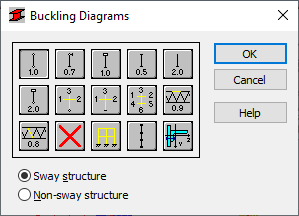
Select one of the icons with the appropriate end support to automatically specify the buckling length coefficient.
The icon colors signify respectively: red - calculations for sway frames, blue - for non-sway frames.
- Typical buckling types
- Typical buckling types are based on the code methods of member support and their corresponding buckling coefficient values.
- Buckling coefficients
 ,
,  ,
, 
- Buckling coefficients are used for the calculation of columns of multi-story frames. They can be used for one, three and six adjoining members. Note: Click any of the buckling length coefficient icons to open the Adjoining Member Parameters dialog.
- Ignore buckling

- Select this icon to ignore the buckling effects during the calculation process. Note: If you don't select this option, buckling is always considered during the calculations when a compressive force acts on a member, even if it is negligible in relation to other internal forces. A separate analysis is not performed to determine whether buckling effects should be excluded or not.
- Automatic buckling length

- Calculates the buckling length of a column according to the automatic procedure
- Internal bracings

- Opens the Internal bracings dialog, which allows you to define the parameters of lateral stiffening.
- This option allows you to consider bars with internal bracings during the calculations. Internal bracings include: lateral stiffening of the analyzed bars, or limiting the buckling length.
- Single angle compression members
 ,
,
- Opens the Single angle compression members dialog which allows you to specify if an angle is a component of a 2D or 3D truss.
- By default an angle is set so that its longer leg is adjacent to the gusset plate, i.e. the axis 'z' parallel to the plane of the plate.
- If you fix an angle to a gusset plate with eccentricity, the program performs calculations based on the section EC5 of the ANSI / AISC 360-05 and ANSI / AISC 360-10 codes.