An Example of Mesh Adaptation
To illustrate the effect of Adaptive Meshing, we have solved for the flow through this industrial water valve:
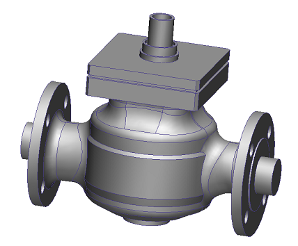
There are several regions in the valve which are not closely bounded by geometry. We can assume there will be flow activity, however, due to the momentum of the water. We will see that the flow recirculates, accelerates, and changes direction abruptly. Because the geometry does not have a great deal of curvature, the mesh may not capture the flow as well as we would like.
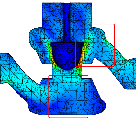
Initial Mesh
In the first meshing cycle, Automatic Mesh Sizing defines a default mesh distribution based only on geometric curvature. Note that the mesh is coarse upstream and downstream of the poppet where there is little geometric influence:
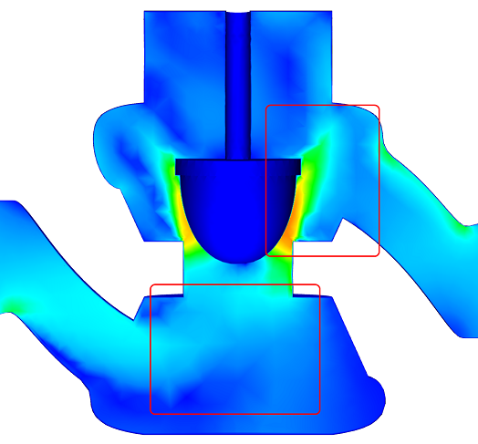
The resultant flow appears jagged because of the sparse mesh distribution. The flow upstream of the poppet is not well defined, and the jet through the annular throat region appears to disperse immediately downstream of the poppet before reattaching to the outlet wall:
Adapted Mesh
After several adaptation cycles, the mesh is refined enough to capture these and other flow features with much greater fidelity:
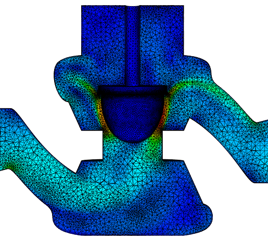
The final results are much clearer, and reflect the physical behavior of the water as it flows through the valve:
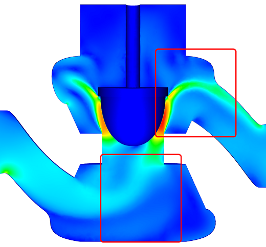
Note the clearly defined flow bifurcation and recirculation upstream of the poppet. The jet through the annulus is very sharp, and it retains its cohesion as it attaches to the outlet wall.
Related Topics:
The following topics describe additional parameters on the Adaptation dialog: