Additional Mesh Adaptation Parameters
The Additional Adaptation controls complement the primary options for defining Mesh Adaptation.
These controls are available on the Adaptation tab of the Solve dialog. To view them, expand the Additional Adaptation list.
Flow Angularity
By default, Mesh Adaptation adapts the mesh based on the field variables (velocity, pressure, and temperature). To improve the resolution in areas that contain large amounts of flow separation and/or circulatory flow, enable Flow Angularity.
Free Shear Layers
Free shear layers occur at the intersection between the free stream velocity and much slower flow such as a wake or separation region. They are characterized by a significant velocity gradient, and the viscous shear stresses are important.
Unlike a shear layer within a boundary layer adjacent to a solid boundary, free shear layers occur within the flow stream. For accurate flow prediction, it is important that the mesh distribution be fine enough to capture the severe velocity gradient within the free shear layer.
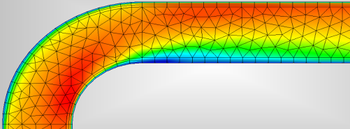
Enable Free Shear Layers if you suspect that such strong velocity gradients will occur within your flow. In the following flow in a bend, a flow separation region occurs at the inside radius of the pipe and the free stream flow core is pushed to the outside radius.
In the following image, the mesh is not adapted for the free shear layer, and the flow in this region is not sharply defined:
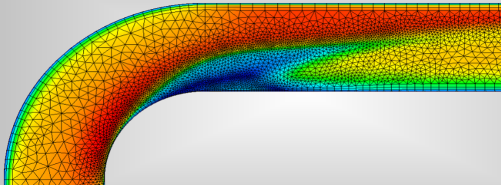
In this image, the mesh is adapted for free shear layers. Notice the sharp distinction of the velocity gradient between the free-stream and the separation region:
External Flow
Enable External Flow when you expect Free Shear Layers to occur in flows that are not closely bounded by walls or other structures. The External Flow option tunes Mesh Adaptation to refine the mesh in high velocity gradient regions occurring between viscous and free-stream flows in large, unbounded flow domains such as those used to simulate aerodynamic flows.
Shocks
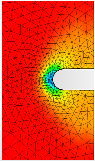
To focus the mesh on the location and gradients across shock waves in compressible flow, enable the Shocks option. In the following image, we can see the shock formation upstream of the object, but because the Shocks option was disabled, the mesh was not adapted to the shock, and the gradients are diffuse:
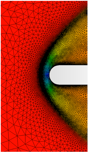
When Shocks is enabled, the mesh adapts based on the formation of the shock, and its location is clearly defined:
Transient Features
If your flow has "dynamic" regions such as a flow reattachment or vortex shedding, enable Transient Features.
This performs three adaptations per error criteria before continuing to the next (tighter) criteria level. The result is that static flow regions are not over-adapted, and dynamic features are better resolved.
Y+ Adaptation
Many turbulent flows, particularly those involving external or aerodynamic flows, are sensitive to the thickness of the boundary elements. The parameter that characterizes this is called "Y+," and is a non-dimensional distance between a wall node and its corresponding neighbor node. This is a component of the Turbulent Law of the Wall.
To allow the boundary element thickness to vary with each adaptation cycle, enable Y+ Adaptation. The Mesher evaluates the Y+ value throughout the model, and reduces the boundary element thickness where values are too high.
The boundary layer thickness does not change at the end of the first adaptation cycle if the simulation had previously been run with Y+ Adaptation disabled:
If you wish to run a preliminary simulation without Adaptation, followed by a series of Adaptation cycles that include Y+ Adaptation, do the following before starting the initial simulation:
- Open the Solve dialog, and click the Adaptation tab.
- Check the Enable Adaptation box.
- Check the Y+ Adaptation box.
- Uncheck the Enable Adaptation box.
This procedure ensures that necessary boundary layer thickness data is stored, and causes the boundary layer thickness to adjust at the conclusion of the first cycle.
Max Y+
According to the Turbulent Law of the Wall and numerous studies, the ideal range for Y+ is between 35 and 350. The default upper limit for Y+ Adaptation is 300. In some demanding cases, (such as very high-speed aerodynamics) it may be necessary to reduce the Max Y+ to achieve the desired accuracy.
Related Topics:
The following topics describe additional parameters on the Adaptation dialog:
Advanced Mesh Adaptation Parameters
To see the effect of Mesh Adaptation on an industrial valve simulation, click here.
Example model showing how to use Mesh Adaptation...