External Passive Cooling
The thermal performance of many passively cooled devices depends on the interaction with the external environment. Unlike actively cooled devices in which an internal fan dominates the cooling, passively cooled devices are cooled through the movement of air outside of the device. To simulate this interaction, an air region is constructed completely around the device.
The air region within the device will be quite small relative to this external volume. In most cases, however, it should be included in the model. The device can be sealed so that this region is disconnected from the outer region, or it can be vented, allowing air to pass from the environment through the device.
As in the other passively cooled configurations, buoyancy is the dominant mechanism of heat transfer. Conduction from heated components to the case is also important, so it is good practice to ensure that physical links are modeled to provide adequate conduction paths.
Applications
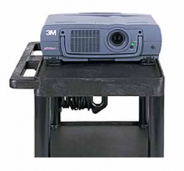
Projector on a table
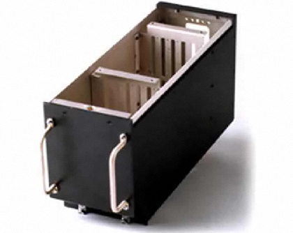
ATR box assembled at the base
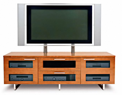
TV or monitor on a table or TV stand
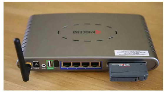
Router, hard-drive, inverter resting on a table or platform
Telecommunications module or transformer suspended from a utility line or pole
![]()
Thermostat mounted to a wall
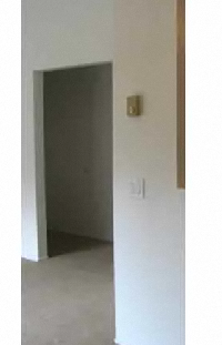
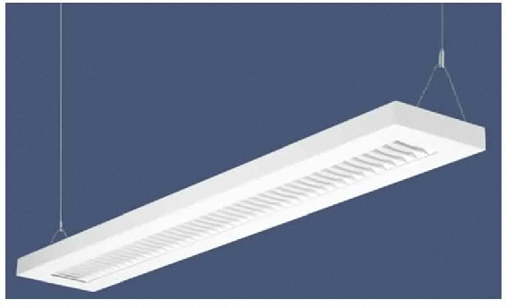
Suspended lighting fixture
Modeling Strategy
There are three primary modeling strategies based on the placement of the device relative to its surroundings: Table-mounted, Air-mounted (such as on a pole or from a wire), and Wall-mounted.
Table-Mounted
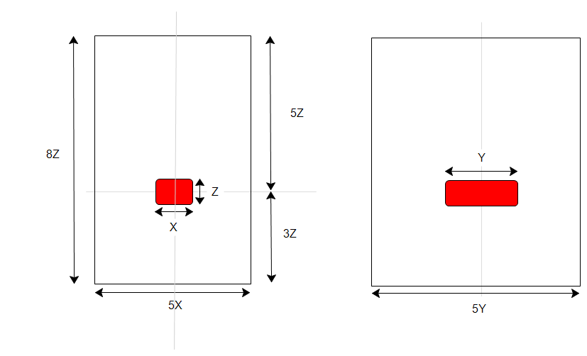
Model a device mounted on a horizontal surface. An example is a router on a table. (This is sometimes called the "bucket" configuration.)
Only the top surface is an opening. Air enters and leaves through this opening. The device usually touches the lower surface of the enclosure.
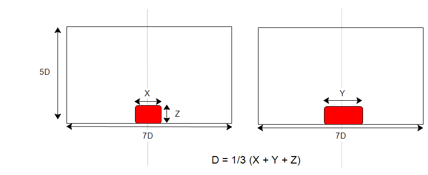
Base the enclosure dimensions on the average of the three dimensions of the device. The stability of the flow is dependent on the aspect ratio of the enclosure. In the case of a long skinny device, this ensures that the environment has a reasonable aspect ratio.
The side view is shown on the left; the front view is shown on the right:
Air-Mounted
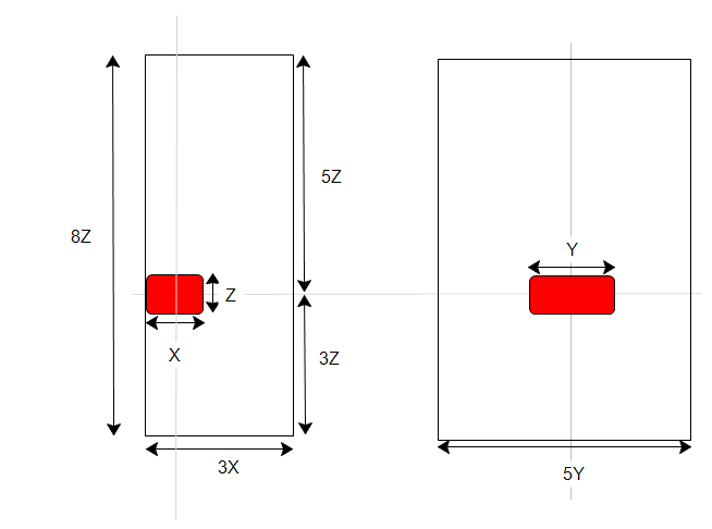
Model a device mounted far from physical boundaries, such as on a pole or from a wire. An example is a telecommunications module suspended from a utility line. (This is sometimes called the "chimney" configuration.)
The top and bottom surfaces are open. Air enters from the bottom and exits through the top.
Construct an enclosure around the device, and center it horizontally within the enclosure. The size of the enclosure should be based on the size of the device, as shown below.
Position the light vertically one third of the total length from the bottom opening.
The side view is shown on the left; the front view is shown on the right:
Wall-Mounted
- Construct an enclosure around the device, and center it horizontally within the enclosure. The size of the enclosure should be based on the size of the device, as shown below. The opposite wall should be three times the dimension perpendicular to the wall. (This is considered a variation of the "chimney" configuration.)
- Position the device vertically one third of the total length from the bottom opening.
- The side view is shown on the left; the front view is shown on the right:
Materials
- Because buoyancy drives the flow, the air material properties must be allowed to vary.
- Assign Air, and set the Environment setting to Variable.
- For very thin enclosures, the heat transfer is largely dominated by thermal conduction instead of convection. In certain applications, it is possible to accurately simulate the heat transfer without having to solve for the flow. Create a custom solid material that has the same properties as air. For more about using the "solid air" material...
- If radiation is included, specify emissivity for the fluid and solid materials. (Note that the emissivity specified for the fluid material only applies to the solid and wall surfaces that the fluid touches.)
- Use material devices to simulate objects such as baffles, internal fans, printed circuit boards, compact thermal models, and thermal electric devices. For more about using material devices...
Boundary Conditions
Table-mounted
- To define an opening (usually the top surface), assign Static Gage Pressure = 0.
- To assign a temperature constraint to the opening, specify a Film coefficient = 2 W/mK 2and Reference Temperature = ambient temperature.
- Leave the bottom surface unspecified to simulate an insulated surface. The exception is if the bottom surface has a constant temperature or if heat is entering or leaving through the surface. Specify a temperature, a heat flux, or a film coefficient, respectively.
- Apply a Total heat generation boundary condition to components that dissipate heat.
Air- and Wall-mounted
To define openings at the top and bottom, assign Static Gage Pressure = 0 to both surfaces
Bottom face (inlet): Static Temperature = ambient temperature
Apply a Total heat generation boundary condition to components that dissipate heat.
Mesh
A basic guideline for a high-quality analysis model is that the mesh distribution be sufficient to resolve the flow and temperature gradients efficiently. In regions where the flow circulates or experiences large gradients (such as in wakes, vortices, and separation regions), a finer mesh is required.
For most models, use Automatic Sizing to define the mesh distribution. It may be necessary to locally refine the mesh on geometric features that are highly detailed. For more information about Mesh Autosizing and model preparation...
In some cases, it may be necessary to adjust the Minimum Refinement Length to reduce their effect on the overall mesh count.
To locally refine the mesh in high-gradient flow regions:
- Adjust the mesh distribution on geometric volumes and surfaces.
- If there are no appropriate geometric features in a particular region, create a mesh refinement region:
- Add one or more volumes in the CAD model.
- Create a Refinement Region from the Meshing task.
Running
Flow = On
Heat Transfer = On
If the component temperatures are relatively high, Radiation = On (Radiation often has a stabilizing effect. In some models, neglecting the effects of radiation produces temperatures roughly 20% higher than actual values.) A useful strategy is to run 200 iterations without radiation, and then enable radiation and continue. This reduces the analysis time, and provides insight into the effects of radiation. Be sure to specify appropriate emissivity material property values. For more about modeling radiation.
Specify a Gravity vector.
Turbulence: The flow in these applications is usually laminar. Click the Turbulence button on the Settings dialog, and select Laminar. If the solution diverges within the first 100 iterations, select the K-epsilon model, and restart the analysis from iteration 0.
Results Extraction
Flow Distribution
Component Temperatures
- Use Results Planes and Iso Surfaces to visualize the flow in and around the fixture.
- Use Particle traces to visualize air movement.
- Display temperature directly on parts and use Results Parts to extract quantitative temperature data.
- Use the Decision Center to compare results from multiple scenarios. Save summary images and create summary items, and evaluate the results in the Critical Values table.
For more general information, use the extensive collection of results visualization tools to extract flow and thermal results.
Troubleshooting
Air-mounted and Wall-mounted
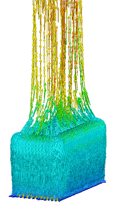
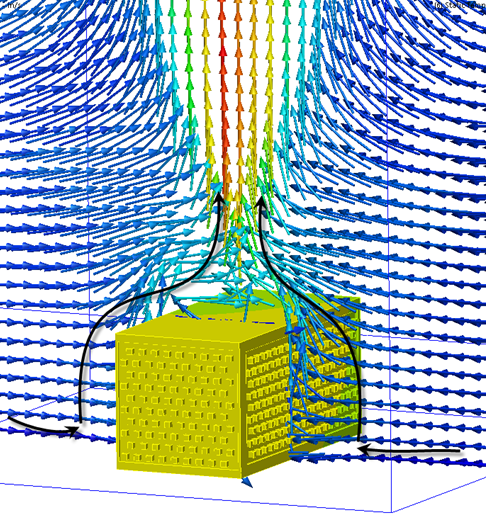
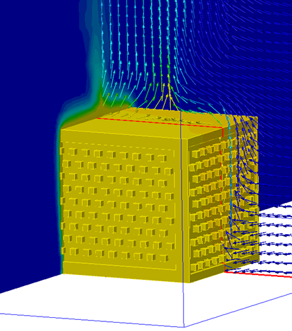
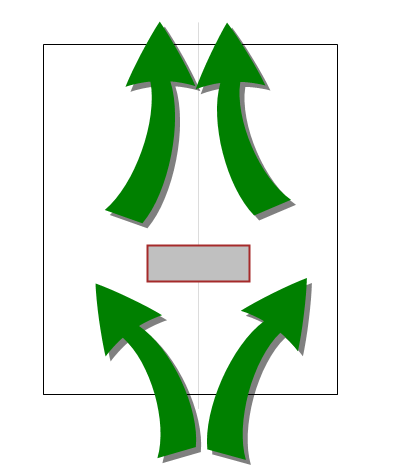
Ideally, the flow should enter through the bottom surface of the region, curve around the device, and accelerate in a plume, as shown on the left. Flow should not enter from the top opening, as shown on the right:
 |
|
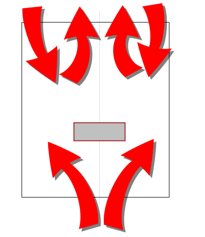
If the flow does enter from the top, there are two recommended corrective actions:
Apply a Film Coefficient boundary condition to the top surface. Specify the Film coefficient = 2 W/mK 2and Reference Temperature = ambient temperature + 1 degree.
Refine the mesh above the fixture. A convenient method is to create amesh refinement region directly above the fixture. The flow gradients will be computed more accurately by focusing the mesh in this region.
Reduce the Local stretching from 1.1 to 1.08. If the problem persists, reduce to 1.05:
On the Mesh task, right click, and select Edit.
On the Mesh quick edit dialog, click the Advanced button.
Change the value in the Local stretching field.
Table-Based
Ideally the flow should enter from the sides of the opening, and exit through the center(forming the plume from the device), as shown on the left. Flow should not enter from just one side and exit near the other side, as shown on the right:
|
|
|
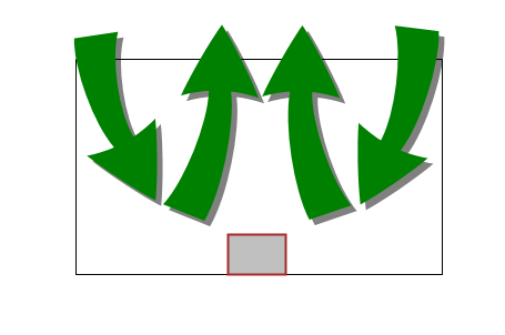
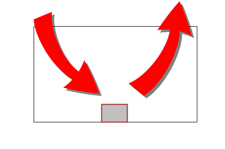
If the flow enters from one side and exits through the other, the recommended action is to refine the mesh above the fixture. A convenient method is to create a mesh refinement region directly above the device. The flow gradients are computed more accurately by focusing the mesh in this region.
Things to Avoid
- Do not apply a film coefficient to the external surfaces of the device. The convective heat transfer from the device to the surrounding air is computed because the surrounding air volume is modeled.
- If the device is vented, do not apply pressure conditions to the vents. These surfaces are internal to the analysis model, so an applied pressure condition is unnecessary. Be sure, however, to apply pressure to the outer surfaces (as appropriate) of the air volume.
- This method can be computationally intensive, especially if a lot of detail is included in the device. Be sure to remove unnecessary detail to ensure efficient modeling.