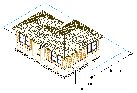
Use this procedure to draw a section line with a section mark at each end. You draw a section line by specifying a start point, an endpoint, a length, and a height for the section. You can specify additional points between the start point and the endpoint to create jogs in the section. The section line acts as a cutting plane, slicing a section from the building model.
- On the default tool palette set, click the Design tab, and then click the Vertical Section tool.
If necessary, scroll the palette to display the tool that you need.
Note: Alternatively, click
 .
. 
- Specify the start point of the section line.
- Continue to specify points to define the section line, if needed.
You can create jogs in the section line to cut through portions of the building model that you want to show in the section, but which are not along a single straight path.
- Specify the endpoint of the section line, and press Enter.

Specifying section line start and end points in 3D view
- Specify the length of the section, or press Enter to accept the length taken from the endpoints of the line.
The section line is displayed in the drawing. Depending on the direction in which you drew the section line, the section marks point in the direction of the section.

The section marks are multi-view blocks, anchored to the section line. You can edit the section marks to change the information displayed in the bubbles.
The height of the section line is set to the extents of the selected objects. You can change the properties of the line to change the height and depth of the section, add a lower extension, or add subdivisions.