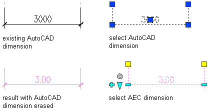
For each AutoCAD dimension point, a non-associative AEC dimension point is created. The resulting AEC dimension has the properties of the AEC dimension tool you select. You can edit these properties after creating the AEC dimension.
- Open the tool palette that you want to use.
- Right-click an AEC dimension tool, and click Apply Tool Properties to
 AutoCAD Dimension.
 - Select the AutoCAD dimensions, and press Enter.
- Do one of the following:
- If you selected one AutoCAD dimension to convert, proceed to Step 7.
- If you selected multiple AutoCAD dimensions to convert, proceed to Step 5.
- Specify the position of the AEC dimension by clicking the desired position in the drawing. The AEC dimension can, for example, be placed above or below the object.
- Do any of the following:
- Drag the mouse to set the direction of the dimension. The extension lines are drawn into the opposite direction.
- To place the AEC dimension perpendicular to a point in the drawing, enter perp (Perpendicular) on the command line, and specify the point the dimension is perpendicular to.
- To set a user-specified angle for the AEC dimension, enter the desired angle on the command line.
Note: The angle you specify here is calculated in relation to the UCS, and not to the dimensioned object. - When prompted to erase the original AutoCAD dimension, press Enter to keep the AutoCAD dimension, or enter y (Yes) to erase it.
The resulting AEC dimension is displayed as follows:
If... Then... you selected only one AutoCAD dimension the new AEC dimension is inserted at the same position as the AutoCAD dimension. If you did not erase the original AutoCAD dimension, the AEC dimension is placed on top of it. you selected more than one AutoCAD dimension the new AEC dimension is inserted according to your specifications from steps 6 and 7. If you did not erase the original AutoCAD dimensions, they remain in their original positions.
