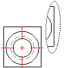
You can use any closed contour (placed on an Inventor linked drawing view) to encapsulates the area to detail.
Note: Inventor Link is available only on 64-bit systems, and it is not installed by default.

Before you begin, create a base view of a part. Make sure you are working in the Drawing tab and the Base View icon in the Browser is highlighted.
- In the drawing area, right-click and choose New View.
- In the Create Drawing View dialog box:
- View Type: Detail
- Scale: Enter a value for the view scale.
- Accept the other defaults, and then choose OK.
- Select the vertex in the base view to attach the detail view.
- On the command line, enter e to create an elliptical viewport border, and then press ENTER.
- Specify the center point for the elliptical area.
- Specify the radius of the X axis.
- Once you define the X axis, move the mouse back and forth or up and down to define the Y axis. You have complete control to create the desired elliptical shape.
- When you have created the desired shape, click the mouse button.
- Specify the location for the detail view by moving the mouse until the elliptical viewport is in the desired location, and then click the mouse button.
- Press ENTER.