When your content is resizable, in effect you have a family of parts/features of various sizes.
The Family Table is a database that contains valid values for parameters that define each member of the family. Each row describes a unique member of the part/feature family.
One of the main uses of the Family Table is to define the valid sizes for the part/feature you are editing. When valid sizes have been defined, whenever you insert the part/feature in a drawing, you are restricted to the defined sizes. Typically you select from a list of valid sizes, at insertion time. When dragging is enabled, the size snaps to a valid size as you drag.
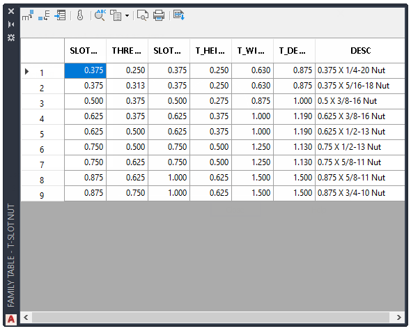
To define the size correctly, you must add each dimensional constraint to the Family Table as a column. Then you add values to each row, like the Family Table shown in the illustration.
Sometimes the value of one dimension is derived from another. For example, consider the T-Slot Nut supplied as a sample custom part.
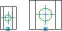
The diameter of the hole grows with the slot size. You simply add the dependant dimensional constraint (the diameter in this example) to the Family Table as a column, and make it a calculated column. In the column properties, you specify the expression to calculate the dimension. Expressions in the Family Table support all the operators, functions, and rules that apply to the Parameters Manager. See the section on Constrain a Design with Formulas and Equations in AutoCAD Help for more information on the rules.
The Family Table can access User Parameters defined in the Parameters Manager. You can add User Parameters as columns, and use the column names in expressions.
If you want the value of a column to be a constant across all rows, you set that column as a Global Column.
Once you put the columns in place, you specify what columns to use as Keys. A Key is a combination of columns that uniquely identify a row in the Family Table. For example, in a screw, its nominal diameter, its pitch, and nominal length together uniquely defines its size. Hence, in the Family Table you select the corresponding columns as key columns. Columns set as key columns are displayed in the list view and tree view in the Predefined Parameters section of the size selection dialog box. In the table view, AutoCAD Mechanical toolset displays all columns that have the Display in Size Selection dialog box option selected.
A Family Table is not limited to defining sizes. For example, you can have two separate rows in the Family Table for 2 screws of identical size, but manufactured from 2 different materials. The dimensions are identical, but the BOM properties are different. SeeAdd BOM specific information for more details on how to use the Family Table to define BOM properties.