Creates angular dimensions.
Find
Summary
List of Prompts
The following prompts are displayed.
Select arc, circle, line or specify vertex
Creates angular dimensions for the object you select.
- Vertex
- Creates a dimension based on three points you specify.
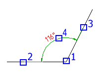
- Vertex - Specifies the point to use as the vertex of the angle (1 in the illustration).
- First angle endpoint - Specifies one of the lines that form the angle (2 in the illustration).
- Second angle endpoint - Specifies the other line that forms the angle (3 in the illustration).
- Dimension arc line location - Specifies where to place the dimension arc line (4 in the illustration). Depending on the position of the dimension, the quadrant for the dimension changes.
- Quadrant - Specifies the quadrant to which the dimension is locked. When quadrant behavior is on, the dimension line extends past the extension line when the dimension text is outside of the angular dimension.
- Arc
- Uses the endpoints of the selected arc and its center as the defining points for a three-point angular dimension. The center of the arc is the vertex.
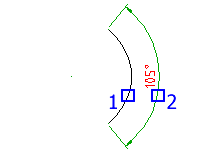
- Dimension arc line location - Specifies where to place the dimension arc line (2 in the illustration). Depending on the position of the dimension, the quadrant for the dimension changes.
- Quadrant - Specifies the quadrant to which the dimension is locked. When quadrant behavior is on, the dimension line extends past the extension line when the dimension text is outside of the angular dimension.
- Circle
- Uses two points on a circle and the center of the circle as the defining points for a three-point angular dimension. The center of the circle is the vertex and the first selection point (1 in the illustration) is the origin of the first extension line.
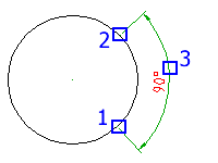
- Second angle endpoint - Specifies the origin of the second extension line (2 in the illustration).
- Dimension arc line location - Specifies where to place the dimension arc line (3 in the illustration). Depending on the position of the dimension, the quadrant for the dimension changes.
- Quadrant - Specifies the quadrant to which the dimension is locked. When quadrant behavior is on, the dimension line extends past the extension line when the dimension text is outside of the angular dimension.
- Line
- Creates a dimension for the angle between two lines. The line you selected (1 in the illustration) is the first line that defines the angle.
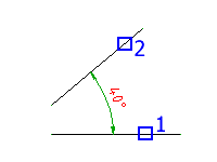
- Second line - Specifies the other line that forms the angle (2 in the illustration).
- Dimension arc line location - Specifies where to place the dimension arc line. Depending on the position of the dimension, the quadrant for the dimension changes. If the dimension line does not intersect the lines you are dimensioning, additional extension lines extend one or both lines. The dimension arc line is always less than 180 degrees.
- Quadrant - Specifies the quadrant to which the dimension is locked. When quadrant behavior is on, the dimension line extends past the extension line when the dimension text is outside of the angular dimension.
Baseline
Creates an angular dimension from the baseline of a selected dimension.
- Base dimension
- Specifies the angular dimension to use as the base for the baseline dimension.
- Next extension line origin
- Specifies the next angle to dimension.
- Select
- Respecifies the dimension to use as the base dimension.
Chain
Creates a linear or angular dimension from the second extension line of a selected dimension.
- Base dimension
- Select the angular dimension to use as the base for the chain dimension.
- Next extension line origin
- Specifies the next angle to dimension.
- Select
- Respecifies the dimension to use as the base dimension.
Options
Displays the Power Dimension Options dialog box enabling you to pre-configure options for this command session.
Note: This option is visible in the command line only if the AMPOWERDIMEDITOR system variable is set to 0 or the ribbon is turned off.