GDT Perpendicularity enables you to determine how close the intersection between a feature and a datum is to a right angle. This example demonstrates how to create a GD&T Perpendicularity item using two planes.
To create a GD&T Perpendicularity item:
- Open a Geometric group in the inspection sequence.
- Click Geometry tab > GD&T panel > Orientation > Perpendicularity.
- Enter a Name for the measurement.
- Click Next to accept the default Angular tolerance. The Feature Definition dialog is displayed. For example:
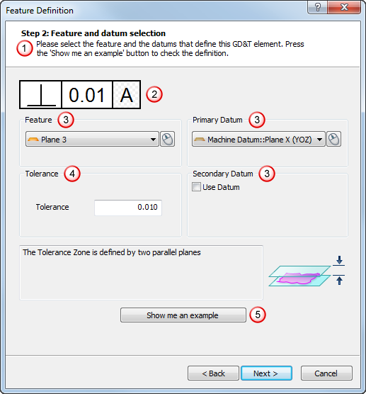
The dialog contains the:
 Instructions, which provide information on how to use the dialog.
 GD&T control frame, which summarizes the GD&T item details. The example shows the Perpendicularity symbol and a tolerance of 0.01 diameters in relation to Datum A. The datum letter is shown against a patterned background to indicate a sequence item is selected as the datum. If a GD&T Datum item is selected as the datum, the background of the box is white.
 Feature and Datum areas, which enable you to specify the feature to be checked and the datums against which it is to be tested. Click
  to select an item from the CAD view using the mouse.
 Tolerance area, where you define the tolerance for the item.
 Show me an example button, which when clicked displays an example diagram for the item in a separate window.
 - Specify the feature settings and the datums and tolerance, then click Next to display the Result Preview dialog. For example:
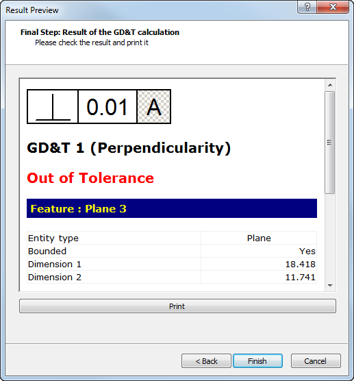
Scroll down to display information about the datum used, the tolerance zone, and error value. For example:
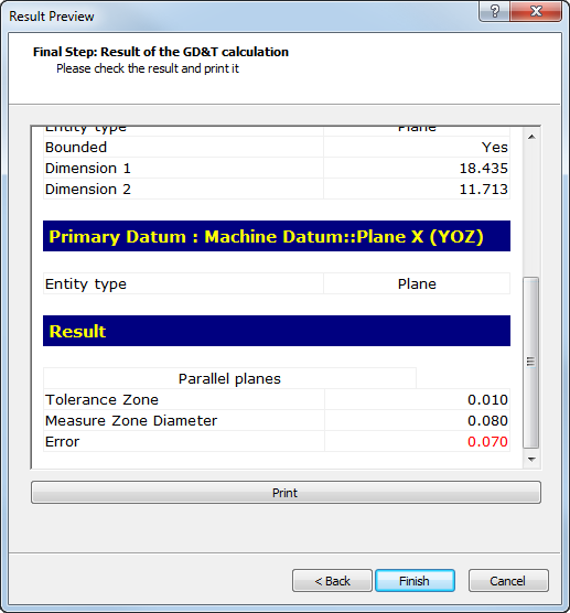
If the Measured Zone Diameter value is less than or equal to the Tolerance Zone plus any bonus you have specified, the measurement is within tolerance. You can add a bonus when you use a maximum or least material condition modifier.
- To print the information, click Print.
- Click Finish to add the GD&T item to the inspection sequence.