To filter the display of the measured points of surfaces in the CAD view, click View tab > View Options panel > Filter Display and select the Surface Inspection tab.
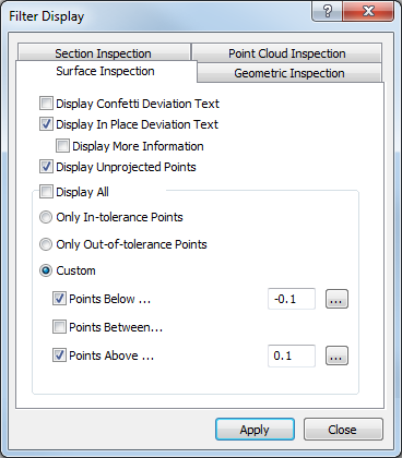
The tab contains the following settings:
- Display confetti deviation text — Select this check box to show the deviation of inspection points alongside confetti in the CAD view. Deselect this check box to show confetti without deviations.
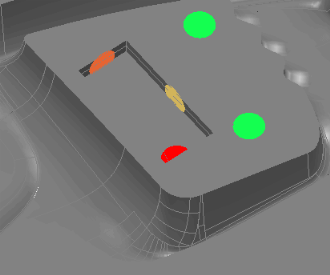
Example of confetti when the Display confetti deviation text check box is deselected:
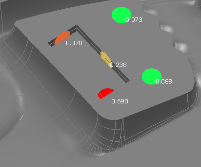
Example of confetti when the Display confetti deviation text check box is selected:
- Display in-place deviation text — Select this check box to show the deviation of inspection points alongside In-place labels in the CAD view. Deselect this check box to show in-place labels without deviations.
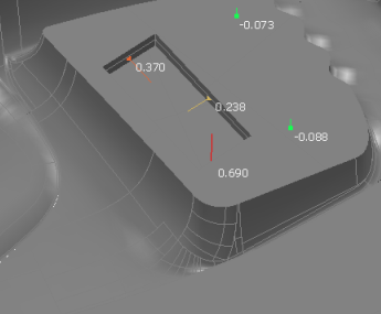
Example of in-place labels when the Display in-place deviation text check box is deselected:
Example of in-place labels when the Display in-place deviation text check box is selected:
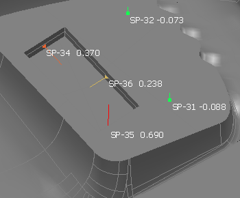
- Display more information — Select this check box to show the name of each probed point when In-place labels is selected. You must select the Display in-place deviation text check box to enable this option.
Example of in-place labels when the Display in-place deviation text and Display more information check boxes are selected:
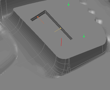
- Display unprojected points — Select this check box to display unprojected points
- Display all — Select this check box to display all surface inspection points. To limit which points are displayed, deselect the check box and then select:
- Only in-tolerance points to display points that are within tolerance.
- Only out-of-tolerance points to display points that are out-of-tolerance.
- Custom to specify the lower and upper limits of the points to be displayed. Select the Points below check box to display points below the specified lower tolerance limit; select the Points above check box to display points above the specified upper tolerance limit; select the Point between check box to display points between the specified upper and lower tolerance limits.
To base a display limit on the tolerances of an inspection group, select the group in the inspection sequence, then click
 .
.
Click Apply to display your changes in the CAD view.