When you select a partial arc, cone, cylinder, or ellipse from the CAD model using Wireframe Checker, PowerInspect displays the nominal Start angle  and End angle
  values in the feature's Inspect dialog.
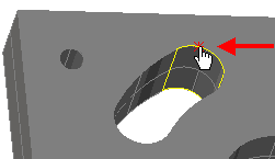
For example, when you select the following arc from a CAD model:
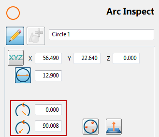
PowerInspect displays the nominal start- and end-angle values on the Arc Inspect dialog:
When you click the Accept  button, PowerInspect creates a sequence item with a probe path determined by the selected probing method. For example:
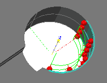
You can use PowerInspect's local coordinate system to help edit the start and end angles for 3D features. The local coordinate system is shown using red, green, and blue dotted lines to represent the X, Y, and Z axes of the feature. For example:
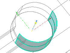
The zero position is the feature's positive X axis. Using the local coordinate system as a visual aid, you can change the start or end angles of the probe path. In the following example, the shaded model shows that the probe path of a cylinder includes touch points that are not in contact with the part:
 Zero position of feature's local coordinate system
 Touch points not in contact with the part
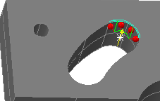
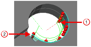
To correct this, change the start angle from -180.00 degrees to -145.000 degrees and save the change. The CAD View updates and shows that all touch points are now in contact with the part: