Best Fit items enable you to use measured surfaces to optimize the alignment of the CAD model with the part. Use them to reduce alignment inaccuracies, to find the Least Material Condition or Maximum Material Condition for the alignment, or to maximize the excess material between the part and the model.
To create a Best Fit item:
- Select the Definition level in the inspection sequence.
- Click Home tab > Create panel > Alignment arrow > Best Fit Alignment.
- Enter a Name for the alignment.
- In the Alignment list, select the alignment you want to adjust.
If a best fit has not been applied to the selected alignment, it is displayed in the Optimized alignment box and the best fit is applied to it. If a best fit has already been applied to the alignment, the latest Best Fit item that contains the selected alignment is displayed in the Optimized alignment box, and it is used in this Best Fit.
- In the Fitting type list, specify the type of adjustment you want to apply to the alignment.
- Best Fit - ignore tolerance band — Select this option to fit the points as close as possible to their nominal position. The points may be above or below the tolerance band.
- MinMax - fit within tolerance band — Select this option to fit as many points as possible within the tolerance band. This may result in some points being further from their nominal positions and a higher overall deviation.
- LMC - fit inside upper tolerance — Select this option to fit as many points as possible below the upper tolerance value and leave the smallest amount of material possible within the tolerance band.
- MMC - fit outside lower tolerance — Select this option to fit as many points as possible above the lower tolerance value and leave as much material on the part as allowable within the tolerance band.
- MaxMin - Maximum smallest deviation — Select this option to maximize the lowest deviation value from the CAD model across all points.
This method maximizes the excess material around the part by shifting the lowest deviation in a positive direction (that is, a negative deviation becomes less negative, and a positive deviation becomes more positive). This means you must select points that completely enclose the part to produce a good fit.
- MaxMin MMC - MaxMin to tolerances — Select this option to find the maximum smallest deviation above the specified lower tolerance.
- If you have not selected a Fitting type of Best Fit, specify the tolerance to be used in the analysis. Select:
- Individual points to use the tolerances of each point.
- Inspection groups to use the tolerances of the selected groups.
- Specify tolerances to use the tolerances entered in the Lower tol and Upper tol boxes.
- In the Maximum iteration box, enter the number of fitting calculations to be performed.
- In the Threshold box, enter a cut-off distance. If the movement between successive calculations is smaller than this distance for all points, the analysis stops. If you enter a distance of less than 0.0001, the value is converted to exponential notation.
- In the Method list, specify the type of transformation that can be applied to the alignment. Select:
- Translation Only to allow only translation. Deselect an Allow translation along check box to prevent translation in that axis.
- Translation and Rotation to allow translation and rotation in all axes.
- 2D Best-Fit to allow rotation around a selected axis, with the point of rotation undefined.
If you want to fix the translation along the vector, select the Lock the translation along the vector check box, and select an entry in the Fixed Plane, Method list to specify the plane normal:
Explicitly Defined — Select a major axis or coordinate type in the Coordinate type list. The probed points are rotated only around this axis. If you select a coordinate type, you must specify the nominal direction using the displayed boxes.
By default, PowerInspect has freedom to translate in all axes. If you want to fix the translation along the vector, click the Lock the translation along the vector option.
Based on Feature — Select the item around which the probed points can be rotated from the displayed list. Alternatively, click
 to select the feature from the CAD view.
 - Rotation Only to only allow rotation around a fixed point.
Select an entry in the Fixed Point, Method list to specify the point:
Explicitly Defined — Select a Coordinate type and then enter the coordinates of the point in the displayed boxes.
Based on Feature — Select the geometric feature that contains the rotation point from the displayed list. Alternatively, click
to select the feature from the CAD view. - Rotational Axis to only allow rotation around a selected axis, with the centre of rotation lying on that axis.
Lock the translation along the vector — By default, PowerInspect has freedom to translate above the selected axis. Select this option to fix the translation along the vector.
Reference Axis — Select the axis around which the CAD model can be rotated. Alternatively, click
to select the feature from the CAD view.
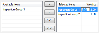
- Add one or more groups to the Selected items list to specify the fitting data. Click:
 to move the selected group from the Selected items list to the Available items list.
 to move the selected group from the Available items list to the Selected items list.
 to move all groups in the Available items list to the Selected items list.
 to move all groups in the Selected items list to the Available items list.
By default, each group in the Selected items list has an equal effect on the fit. To assign greater emphasis to a group's measurements, click the group, click the weight value, and then type a multiplier in the entry box.
For example, if you enter a weight of 2.00 for Inspection Group 1, the effect is the same as entering each point into the calculation twice. This doubles the effect of the group on the residual error:
- To include the item in the report, select the Output in report check box.
- Click OK to save your changes and close the dialog. When the selected groups are measured, run the Best Fit Analyser to optimize the alignment.