Use Edge Points On-the-Fly to manually inspect the boundary of a surface. To measure an edge point you must take a point on the surface near the edge you want to inspect, followed by a point against the edge.
To probe edge points on the fly:
- Open an On-the-fly Edge Group.
- Click Form tab > Edges panel > On-the-Fly Point. The Edge Points On-the-fly dialog is displayed.
- Probe a point on the surface near the edge you want to inspect.
A yellow triangle is displayed on the part in the CAD view to indicate where you must probe the edge of the surface. The coordinates of the point are displayed on the left of the Edge Points On-the-fly dialog.

- Move the probe to the location indicated by the yellow triangle, and take the point. The deviation of the edge point from the CAD nominal is displayed on the right of the
Edge Points On-the-fly dialog.
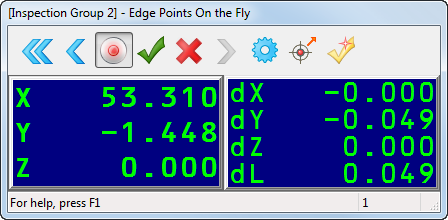
The colour of the dL value and the triangle displayed in the CAD view indicate whether the point is within tolerance (green), below tolerance (blue), or above tolerance (yellow).
- Click
 to save the edge point measurements and probe the next edge point.
- Repeat steps 4 to 5 to measure more edge points.
- When you have finished probing, click
 to save the points and close the dialog.
To view the details of a measurement, select a point in the inspection group, and then select the Info tab.