CNC Edge groups measure edges of a part by following a probe path. Use them when you want to automate the inspection, or when you want to ensure the same points are probed in each Measure of a document.
Note: CNC Edge groups are available only when creating inspections for CNC and OMV machines.
To create the probe path for a CNC Edge Group:
- In the Features tab, deselect the Generate Probe Path button.
- Click Hometab > Create panel > Form > CNC Edge Group. An inspection group is added to the inspection sequence and the Edge Inspect dialog is displayed in the Features tab.
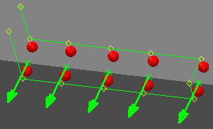
- In the Edge Inspect dialog, select the AutoTouchTrigger probing method with which you want to generate the probe path. Select:
- SurfaceSurfaceProbing to probe all the surface points before probing the corresponding edge points. For example:
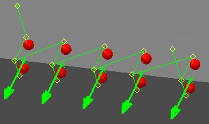
- SurfaceEdgeProbing to alternate between probing surface and edge points. For example:
- SurfaceSurfaceProbing to probe all the surface points before probing the corresponding edge points. For example:
- Position the cursor on the CAD model near the edge you want to inspect. When a triangle is displayed along the edge, double-click the model to specify the location of a probe point.
- Repeat step 4 to add more points.
- Complete the parameters in the Edge Inspect dialog, and then click
 to create the group.
Note: Before running the inspection, check the approach and retract distances for the group and adjust them if necessary.
To view and update the group settings, right-click the group in the inspection sequence, and select Modify item from the context menu.