The Point Cloud Picked-Points alignment enables you to align a part to the CAD model by matching target points on the CAD to selected regions in one or more point clouds. The point clouds must cover at least three faces of the part so that the target points can fix the six degrees of freedom.
To create a picked points alignment from a point cloud:
- In the CAD view, display the model and the point clouds you want to use to create the alignment.
- Select the Definition level in the inspection sequence.
- Click Alignments & Datums tab > Alignments panel > Point-Cloud Picked-Points. The
Point Cloud Picked-Points Alignment dialog is displayed.
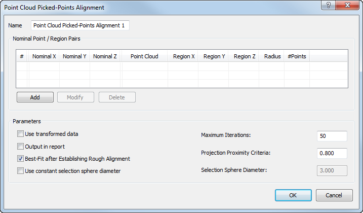
- Enter a Name for the alignment.
- To use a constant-sized region for each target point, select the Use constant selection sphere diameter check box and enter a Selection Sphere Diameter to specify the region size.
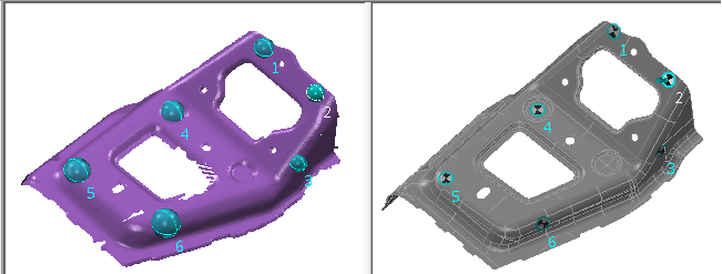
- Click Add to select the target points on the model and their corresponding point cloud regions. The Pick Target / Regions dialog is displayed, and the CAD view displays the model and the visible point clouds in split-screen mode one above the other.
- Adjust the views:
- To display the model and point clouds side-by-side, select
 .
.
- To change the view of the model or point clouds, use the View tab.
- To apply your changes to both views simultaneously, select
 .
.
- To display the model and point clouds side-by-side, select
- In the Pick Target / Regions dialog, click the Show coordinates check box to display the details of your selections.
- Specify a target-region pair that can be used to create the alignment:
- Double-click the model to select a target for the alignment. An arrow and target
 are displayed at the location, and the coordinates of the target are displayed in the coordinates list.
- Left-click and hold the point cloud at the centre of the region that matches the target, drag the cursor to select points from the point cloud, then release the mouse button. Alternatively, if you selected the
Use constant selection sphere diameter check box, double-click the point cloud.
A sphere
 is displayed to show the region of the point cloud you selected. The name of the point cloud, the region centre, the region radius, and the number of points in the region are displayed in the coordinates list in the same row as the associated target.
- Double-click the model to select a target for the alignment. An arrow and target
- Repeat step 9 to create at least six target-region pairs using the
3-2-1 rule to lock all six axes on the part.
For example:
- When you have specified the target-region pairs for the alignment, click
 to save your selections and close the dialog.
- To create an alignment from point clouds taken by different measuring devices or from different device positions, select the Use transformed data check box. PowerInspect converts the device coordinates to CAD coordinates so that the calculations are made using a common reference system.
- To display the alignment in the CAD view, and on the Report and Info tabs, select the Output in report check box.
- In the Projection proximity criteria box, enter the maximum distance a point can be from the CAD surface. If a point exceeds this distance, it is ignored.
- To optimize the alignment:
- Select the Best fit after establishing rough alignment check box.
- In the Maximum iterations box, enter the maximum number of times you want PowerInspect to perform the best-fit calculations.
- Click OK to save your changes and create the alignment.