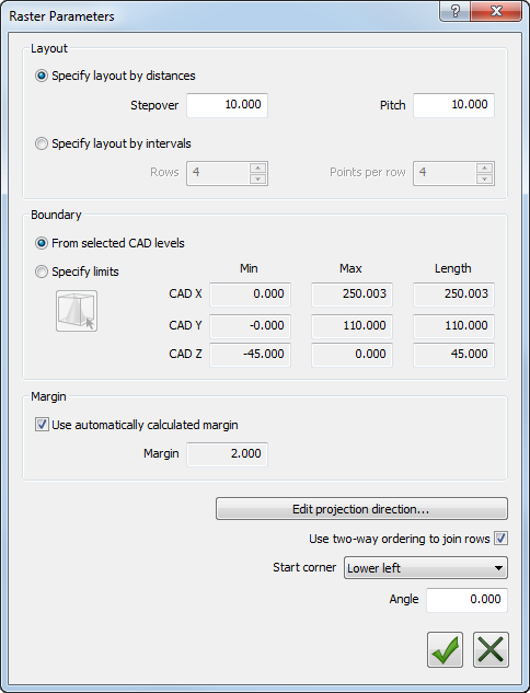
The Raster probing method enables you to generate a probing pattern for use with surface inspection groups. Use the Raster Parameters dialog to specify the density of points in the pattern and the extent of the probe path created.
To change the parameters for the Raster probing method:
- Select the
Raster method, and click the
Parameters
 button. The
Raster Parameters dialog is displayed.
button. The
Raster Parameters dialog is displayed.
- In the
Layout area, specify how the rows in the probe path are created. Select:
- Specify layout by distances to control the distance between each point.
In the Stepover box, enter the distance between each row in the probe path; in the Pitch box, enter the distance between the points in each row of the probe path.
- Specify layout by intervals to control the number of points.
In the Rows box, enter the number of rows in the probe path; in the Points per row box, enter the number of points in each row.
- Specify layout by distances to control the distance between each point.
- In the
Boundary area, specify the extent of the probe path. Select:
- From selected CAD levels to restrict the probe path to the CAD levels selected in the Custom levels area of the Inspection Group dialog. If no custom levels are specified in the group dialog, PowerInspect uses the active levels specified in the CAD tab.
- Specify limits to restrict the probe path to specified boundaries. To specify the boundaries, enter the
Min,
Max, and
Length values for the probe path in each major axis of the CAD model.
Alternatively, click the Edit Graphically
 button and use the box displayed in the CAD view to restrict the path boundaries.
To move the box, position the cursor over a yellow line, and, when the cursor changes to
 , left-click and drag.
To change the size of the box, position the cursor over a blue line, and, when the cursor changes to
 , left-click and drag. For example:
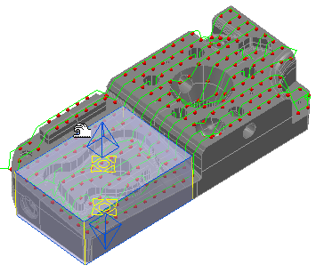
The positions and sizes of the boundaries are displayed in the Edit Boundary dialog. Any points outside the boundaries are excluded from the probe path. To adjust the shading of the box, move the Opacity slider in the Edit Boundary dialog.
- By default, PowerInspect calculates the margin of the probe path from the size of the probe. To specify the margin, deselect the Use automatically calculated margin check box and type the new value in the Margin box.
- By default, PowerInspect projects the probe path onto the CAD model in the Z+ direction. To project points in a different direction, click Edit projection direction and create a transformation to change the vector.
- Select the Use two-way ordering to join rows check box to alternate the direction of the probe path between rows. Deselect the check box to use the same direction for each row.
- In the Start corner list, select the corner at which you want the path to start.
- By default, the rows run parallel to the model's X axis. To change the row direction, enter a value in the Angle box. A positive value rotates the path counter-clockwise; a negative value rotates clockwise.
- Click the
OK
 button to save your changes.