Use Guided Surface Points to position inspection points on a part exactly. Use them when you want to measure mandated positions on a surface, or when you want to ensure repeatability across different Measures.
To create a guided surface point:
- Open a Guided Surface Points group.
- Click Form tab > Surfaces panel > Guided Point.
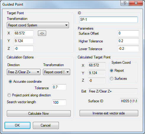
- In the ID box, enter a name for the point.
When the Use surface projected onto as point name prefix check box in the Options dialog is selected, points are automatically named after the surface onto which they are projected, and you cannot change the ID.
- To compensate for the thickness of the part's surface, enter a Surface offset value.
The offset value can be used to compensate for the thickness of the pressing (usually a positive value), or the spark gap for an electrode (usually a negative value). The offset is applied normal to the surface at the probed point, with positive values in the direction of the probe.
You can apply an offset value to all points in a group in the Inspection Group: Guided Surface Points dialog.
- In the Higher tolerance and Lower tolerance boxes, enter the maximum distances from the nominal surface at which the point is in tolerance.
- In the Target Point Transformation list, choose the coordinate system in which you want to enter the location of the point. Select:
- Report coord system to specify the coordinates relative to the CAD datum.
- Surface coord system to specify the coordinates relative to the Machine datum.
- In the X, Y, Z boxes, enter two or three nominal coordinates for the point.
Click
 to transform the coordinates to the alternative coordinate system.
 - If you specified three coordinates for the point:
- Select Accurate coordinate.
- In the Tolerance box, enter the maximum distance by which the point can vary from the nominal. Points exceeding this distance from the nominal are not created.
- If you specified two coordinates for the point:
- Select Project point along direction.
- In the Search vector length box, enter the maximum distance along the axis of the unspecified coordinate at which the point can be projected onto the model. Points exceeding this distance from the nominal are not created.
- In the Direction list, select the direction from which the point will be probed.
- In the Calculation Options Transformation list, choose the coordinate system for the calculated position of the point. Select:
- Report coord system to calculate the coordinates relative to the CAD datum.
- Surface coord system to calculate the coordinates relative to the Machine datum.
- Click Calculate Now to check that the coordinates lie on a surface and to project the point onto the model. If the point is valid:
- The Calculated target point area displays the nominal position of the point. Select a System coord option to choose the coordinate system in which the position is displayed.
- The Exit box displays the probe's clearance direction relative to the selected System coord. Click the Inverse Exit Vector Side button to reverse the direction.
- The Surface ID box displays the name of the surface onto which the point is projected.
- Click OK to create the point and close the dialog.
When you play a guided surface point, a target is displayed in the CAD view so you can accurately position the probe. PowerInspect identifies the nearest location on the model and uses this to reset the position of the nominal. The updated nominal is then used to calculate the deviation of the measured point.