You can create chamfers on the edges of a solid.
To create a solid chamfer:
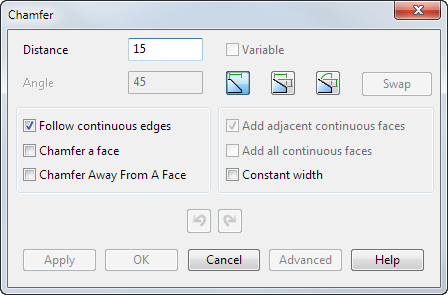
- Click Solid tab > Feature panel > Fillet > Chamfer to display the
Chamfer dialog:
If your version 8 solid contains more than 20 surfaces and is not watertight, you are asked if you want to make it watertight. If you click Yes, the Make Watertight Wizard appears to help you make the solid watertight (within tolerance).
- Enter the
Distance to be used to create the chamfer as shown below:
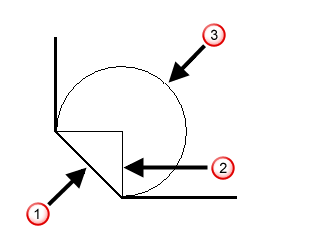
 Chamfer
 Distance
 Arc with radius equal to distance
- Use one of the following options to specify the chamfer:
- Select the chamfering route:
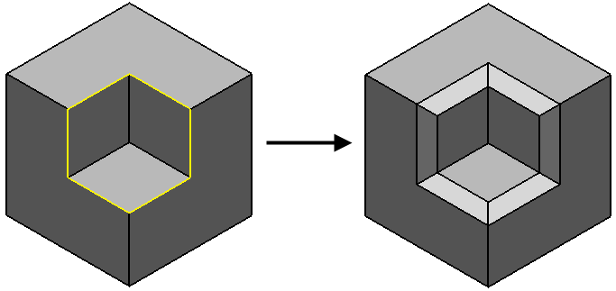
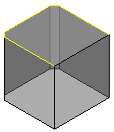
- Follow continuous edges — Select this option and hold the cursor over a valid edge, before a path is selected. A path is highlighted containing that edge and all edges which are tangent continuous with that edge.
If you select an edge, a new path is selected containing that edge and all edges which are tangent continuous with that edge.
The edge shown below is selected.
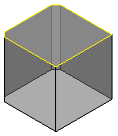
The following path is selected.
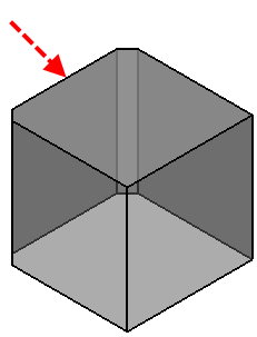
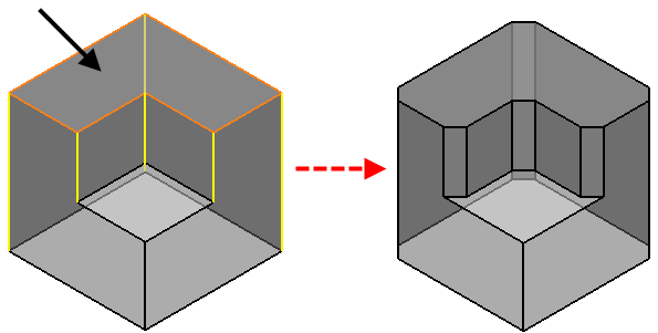
- Chamfer a face — Select this option and hold the cursor over a valid edge, before a path is selected. A path is highlighted containing all edges of a face of the solid which contains that edge.
If you select an edge, a new path is selected containing all edges of a face of the solid which contains that edge.
The edge shown below is selected.
The following path of face edges is selected.
- Chamfer Away From A Face — Select this option, then select a face on the model to highlight all the edges to be chamfered. The highlighted tracks are chamfered when you click
Apply.
- Variable — This option is only available when you have clicked Apply to create a chamfer. If you have selected the path, but not created the chamfer, you can select the Advanced button to create a variable distance chamfer.
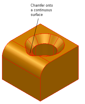
- Add adjacent continuous faces — Select this option if a chamfer cannot be created because it spreads onto neighbouring surfaces.
The chamfer does not spread beyond the neighbouring surfaces. To spread the chamfer beyond onto all surfaces, use the Add all continuous faces option.
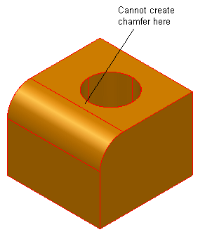
This option allows you to create the chamfer onto the continuous surfaces.
- Add all continuous faces — This is the same as the
Add adjacent continuous faces, except the chamfer can spread onto all surfaces that are tangent plane continuous.
This option may be much slower when creating chamfers. We recommend you use the Add adjacent continuous faces if you recognise that a chamfer will not spread beyond its neighbouring surfaces.
Deselect the option when you have finished using it.
- Constant width — When you create a chamfer, the width of the chamfer varies to reflect the angle between the surrounding faces. Select Constant width to create a constant width for a chamfer.
 —
Undo / Redo
a chamfer. The normal undo behaviour is retained when the dialog is closed. That is, selecting Home tab > Delete panel > Undo immediately after creating a chamfer or group of chamfers removes the created chamfers.
—
Undo / Redo
a chamfer. The normal undo behaviour is retained when the dialog is closed. That is, selecting Home tab > Delete panel > Undo immediately after creating a chamfer or group of chamfers removes the created chamfers.
- Follow continuous edges — Select this option and hold the cursor over a valid edge, before a path is selected. A path is highlighted containing that edge and all edges which are tangent continuous with that edge.
- Click
Apply to create a chamfer along the selected path.
A Chamfer feature icon
 representing the operation appears in the solid feature tree.
You can now either edit the distance of the chamfer just created or select more edges to create another chamfer.
- Click Advanced while a path is selected to create a variable distance chamfer. The Variable Distance Chamfer dialog is displayed. Use this dialog to insert lines along the path to define the different distance values.
- Click OK to close the dialog.
 —
—
 —
—
 —
—