Specify settings for contour line display, on toposolid family types.
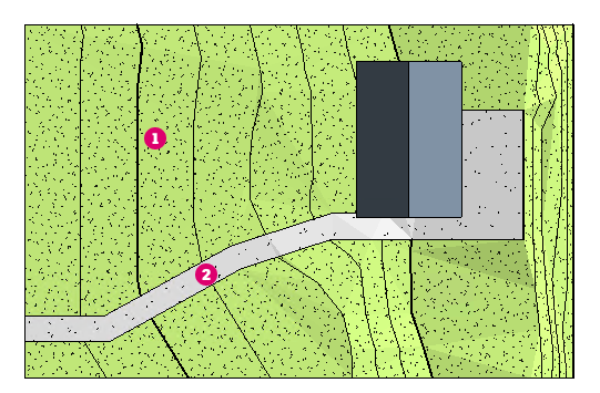
Contour display on toposolid elements is controlled by the type properties. This allows you to use different toposolid elements to represent different site features of your design. For example: One toposolid type represents the general site conditions and displays contour information
 . Another toposolid type representing a patio and sidewalk does not display contour information
 .
.
. Another toposolid type representing a patio and sidewalk does not display contour information
.
Note: Use
Visibility and Graphics to conntrol contour display for all toposolids in a view.
To define contour display settings for a toposolid type
- In the drawing area, select a toposolid, and on the Properties palette, click
 Edit Type.
- In the Type Properties dialog, click Edit next to the Contour Display parameter.
- In the Contour Display dialog define the contours for the toposolid type. Click Insert for each set of contour lines.
- Specify the Start, Stop, and Interval for the contour lines.
- Set Range Type. Use Multiple Values for a set of contour lines displayed at regular intervals. Use Single Value to establish one contour line at a specific elevation.
- For Subcategory, specify the line style for the contour lines.
- Clear the selection box for a row to turn off visibility of a contour range.
Note: The following table describes the settings used for contour definition in the Contour Display dialog:Name Description Start Sets the elevation where contour lines begin. Stop Sets the elevation where contour lines no longer display. Interval Sets the interval for contour lines. Range Type Select Single Value to insert one contour line. Select Multiple Values to insert incremental contour lines. Subcategory Sets the type of contour lines to display. Select a value from the list. To create a custom line style, open the Object Styles dialog. On the Model Objects tab, change settings under Topography. - Click Ok twice to apply changes to the toposolid.