11. Create and Insert Blocks
Blocks are compound objects that are commonly used for symbols, parts, detail views, and title blocks.
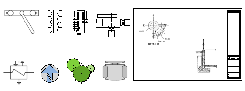
A block is one or more objects combined to create a single object. The following are some examples of blocks inserted into a drawing.
Using blocks provides the following advantages:
You can ensure uniformity between identical copies of furniture, fixtures, parts, symbols, and title blocks in drawings.
You can insert, rotate, scale, move, and copy blocks much faster than operating on selections of individual geometric objects.
If you edit or redefine a block definition, all block references in that drawing are updated automatically.
You can include data such as part numbers, costs, service dates, and performance values to blocks. The data is stored in special objects called block attributes.
You can reduce the file size of a drawing by inserting multiple block references instead of duplicating object geometry.
With online access, you can download AutoCAD drawing files from the web site of commercial vendors and suppliers. This option can save you a significant amount of time but check to make sure that these drawings are drawn correctly and to scale.
There are four things involved for inserting blocks in a drawing.
A block definition. This data is stored in a drawing file or drawing template file in a non-graphical format. Block definitions can easily be created or imported from any drawing file. Multiple block definitions can be created in a drawing file.
Note:Block definitions don't always need to be created just in the drawing that they will be used. A drawing file itself can represent a block definition that can be shared with other designers and inserted into any open drawing file.
A block reference. When you insert a block, you specify which block definition to create an instance. The graphics for the block reference are generated from the block definition. A drawing file can also be inserted into an open drawing, when this happens a block definition based on the geometry in model space of the drawing file being inserted is created in the target drawing and then a block reference is created.
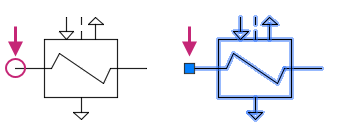
A block insertion base point or just base point. When you insert a block, this is the part of the block reference attached to your cursor.
The base point is circled on the block below. Later, if you select a, block that's already been inserted, it displays a grip at the base point. You can easily move and rotate this block using this grip.
A block insertion tool. Several different tools are available in the product. These include the block gallery on the ribbon, the Blocks palette, the Tool Palettes window, and DesignCenter.
These block insertion tools allow you to insert block definitions created within the current drawing as well as insert drawing files stored on your local workstation or a shared network location.
The following videos demonstrate some of the learning objectives covered in this topic:
Some of the concepts mentioned in the videos are not covered in this topic. For more information on dynamic blocks and annotative behavior, see About Dynamic Blocks and About Annotative Objects and Styles in the product help.
Learning Objectives
Prerequisites
You should know how to do the following before continuing:
- Create, open, save, and view drawings
- Work with commands
- Create basic 2D objects (lines and circles)
- Select, modify, and duplicate objects
Prepare for the Exercises
To follow along with the exercises in this topic, download the ZIP file containing the sample drawings.
![]() Download: Sample drawing files used for the following exercises
Download: Sample drawing files used for the following exercises
The ZIP file contains all drawings used for the exercises and only needs to be downloaded once. Keep the ZIP file to restore the original state of the sample drawings.
Insert a Block Reference
Typically, you insert a block into the current drawing from one of these sources:
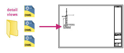
Any drawing file. For example, you might create a drawing of a standard detail view. You can then use a block insertion tool to insert this drawing as a block into your current drawing. In this example, the detail views folder is commonly termed a block library folder.
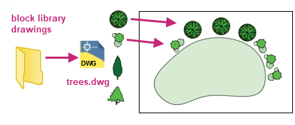
One or more block definitions contained within a drawing file. For example, you can create a drawing that only contains block definitions of trees. You can then insert any of these blocks from that drawing into your current drawing. A drawing file that contains related blocks is commonly termed a block library drawing.
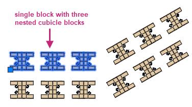
One or more block definitions created in your current drawing. For example, you might want to create a block from a set of objects that appear repeatedly in that drawing, such as the following cubicle arrangement that contains multiple nested blocks. All the blocks used in the cubicle arrangement can be combined into a single block for multiple insertions.
Once you insert a block, you can easily move, copy, rotate or scale it as a single object.
Try It: Insert a Block Reference
Insert two blocks using different methods: AutoCAD Design Center and the Blocks palette.
- On the Quick Access toolbar, click Open.Find
In the Select File dialog box, browse to the sample files you previously downloaded and select the Office Plan.dwg file. Click Open.
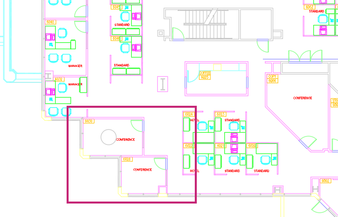
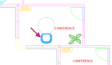
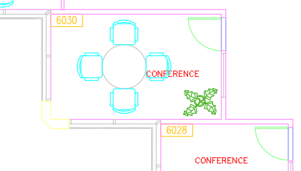
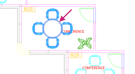
In the drawing area, zoom to the area indicated in the following image.
You should see several workstations and conference rooms, one of the conference rooms contains a circle (table).
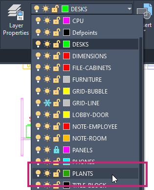
On the ribbon, click Home tab > Layers panel > Layers drop-down list and choose PLANTS.
- Click View tab > Palettes panel > DesignCenter.Find
On the DesignCenter palette, click over the title bar of the palette and drag the palette so you can see the conference room with the circle (table).
Tip:The palette can be resized by moving the cursor to the top, bottom and opposite edge of the title bar. Click and drag when the cursor appears as a double sided arrow.
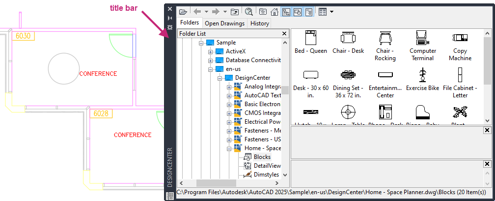
Click the Folders tab and navigate to <drive>:\Program Files\Autodesk\AutoCAD <version>\Sample\<language>\DesignCenter.
For example, the location for AutoCAD 2025 English on the default drive is C:\Program Files\Autodesk\AutoCAD 2025\Sample\en-us\DesignCenter.
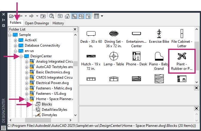
In the Folders tree view, left-side of the palette, click the + next to the DesignCenter folder and then the Home - Space Planner.dwg file. Select the Blocks node under the Home - Space Planner.dwg file.
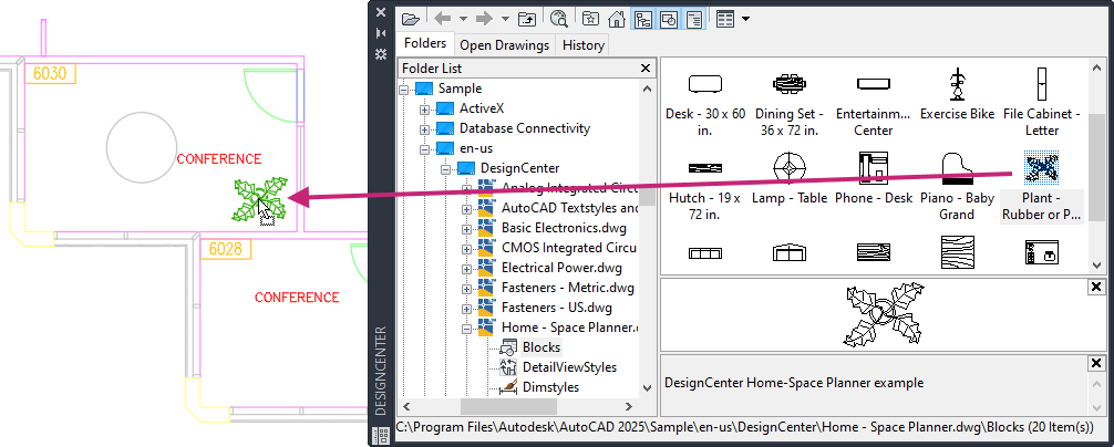
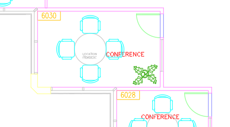
In the Content area, right-side of the palette, select and drag the Plant block into the lower-right corner of the conference room. Release the mouse button to insert the block.
On the DesignCenter palette, title bar, click Close.
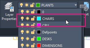
On the ribbon, click Home tab > Layers panel > Layers drop-down list and choose CHAIRS.
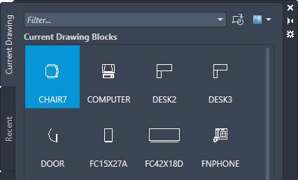
- Click View tab > Palettes panel > Blocks.Find
On the Blocks palette, Current Drawing tab, under the Options section:
Clear all check boxes.
Click the Insertion Point and Rotation check boxes.
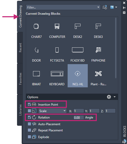
Under the Current Drawing Blocks section, click CHAIR7.
After clicking of CHAIR7 from the palette, insertion of the block begins.
Move the cursor near the circle (table) in the conference room labeled 6030.
- Hold down the Shift key and right-click. From the context menu, choose Quadrant.

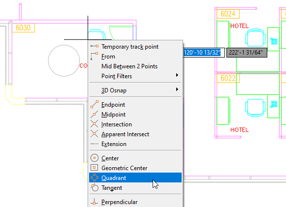
Move the cursor and snap to the quadrant at the bottom of the circle (table).
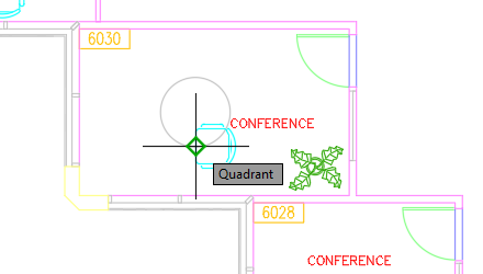
At the Specify rotation angle <0.00>: prompt, enter -90.
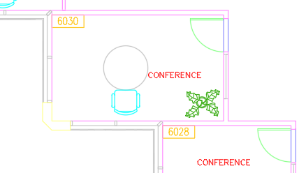
While you could continue by manually inserting three more chair blocks around the table, its more efficient to create a polar array of the chair block instead. You will learn how to create this polar array in the next exercise.
- On the Quick Access toolbar, click Save.Find
Create a Block Definition
You can create blocks by associating objects and then giving them a name, or by creating a drawing to be used as a block.
A block definition includes its geometry, layers, colors, linetypes, and block attributes. Whenever you create a block or insert a drawing as a block, all this information is stored in the drawing file as non-graphic information.
Whenever you create a block or insert a drawing as a block, all this information is stored in the drawing file as a block definition. A block definition includes the geometry that visually defines how the block should look when inserted into a drawing. When a block is inserted into a drawing, it is known as a block reference. A block reference identifies where a copy of that block definition should be located, oriented, and scaled in the drawing. Block references are often simply called blocks.
Blocks can be created and saved in several places:
- Within a drawing file intended for use only within that drawing.
- Within a drawing template file intended for creating new drawings.
- As separate drawing files intended to be inserted into other drawings as blocks.
When creating geometry for a block, the geometry within the block can inherit its properties from their assigned layers as well as the layer on which the block is inserted. When the properties of geometry are assigned a ByBlock value, the object inherits its properties from the layer assigned to the block. Geometry placed on layer 0, when added to a block, also inherits its properties from the layer assigned to the block. For more information, see the Block Object Properties Reference topic in the product help.
Try It: Create a New Block Definition
Array a chair block around a circle and create a block that represents a conference table with four chairs.
Continue with the Office Plan.dwg file from the previous exercise: Try It: Insert a Block Reference.
Create a polar array of four chairs around the table. This can be done by doing the following:
- On the ribbon, click Home tab > Modify panel > Array drop-down menu > Polar Array.Find
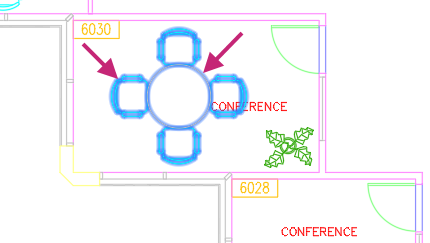
At the Select objects: prompt, select the chair block indicated in the following image and press Enter.
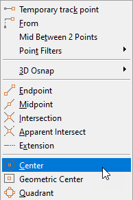
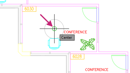
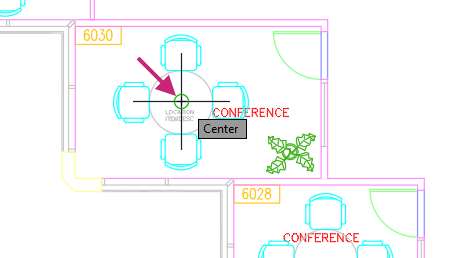
- At the Specify center point of array or [Base point/Axis of rotation]: prompt, hold down the Shift key and right-click. From the context menu, choose Center.

Specify the center point of the circle adjacent to the chair for the center point of the array.
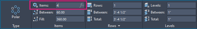
Click Array Creation contextual tab > Items panel, click in the Items text box and change the value to 4, and then press Enter.
At the Select grip to edit array or [ASsociative/Base point/Items/Angle between/Fill angle/ROWs/Levels/ROTate items/eXit]<eXit>: prompt, press Enter.
Create a block definition of the table and four chairs. This can be done by doing the following:
- Click Insert tab > Block Definition panel > Create/Write Block drop-down menu > Create Block.Find
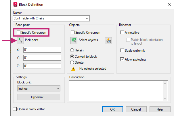
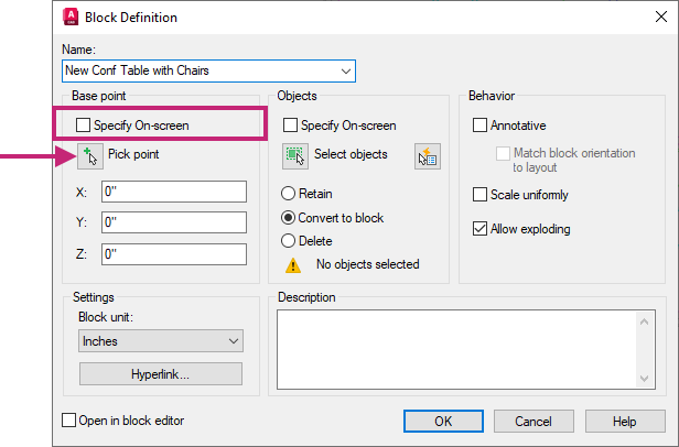
In the Block Definition dialog box, Name text box, type Conf Table with Chairs.

Under Base Point,
Clear the Specify On-Screen check box.
Click Pick Point.
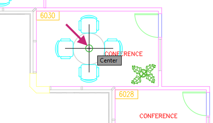
- At the Specify insertion base point: prompt, hold down the Shift key and right-click. From the context menu, choose Center.
Specify the center point of the circle.
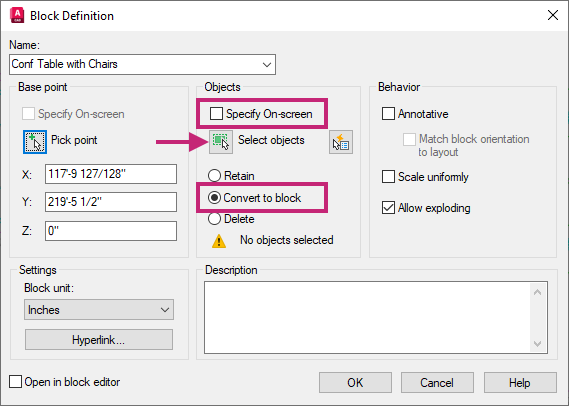
Under Objects,
Clear the Specify On-Screen check box.
Choose the Convert to Block option.
Click Select Objects.
At the Select objects: prompt, select the circle and array of chairs, and then press Enter.
Click OK.
Select the circle with the chairs around it.
You should notice the circle and four chair blocks are selected, this is because the objects were replaced by the new block definition named Conf Table with Chairs.
With the block selected, on the ribbon, click Home tab > Layers panel > Layers drop-down list and choose FURNITURE.
The block is placed on the FURNITURE layer.

Press Esc to deselect the selected block reference.
- On the ribbon, click Home tab > Layers panel > Make Current.Find
At the Select object whose layer will become current: prompt, select the Conf Table with Chairs block reference in the 6030 room.
The FURNITURE layer is made current. This can be faster than selecting a layer from the Layers drop-down list on the ribbon, especially if you don't know the layer you want to set as current but know of an object that is on the layer.
- If the Blocks palette is closed, on the ribbon, click View tab > Palettes panel > Blocks.Find
On the Blocks palette, Current Drawing Blocks tab, click Conf Table with Chairs.
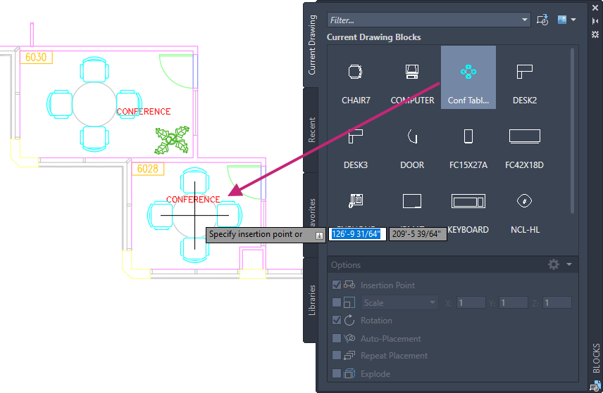
At the Specify insertion point or [Basepoint/Scale/X/Y/Z/Rotate]: prompt, specify a point near the middle of the adjacent conference room to insert a reference of the new Conf Table with Chairs block.
Tip:If you want to place it at the midpoint between two corners, you could use the Mid Between 2 Points option on the Object Snap right-click menu.
At the Specify rotation angle <0.00>: prompt, press Enter to accept the default rotation angle.
- On the Quick Access toolbar, click Save.Find
Store Information in Blocks with Attributes
Blocks allow you to create identical instances of the same geometry and text, but there are situations where you might want the text to vary between block references. For example, you might want to create a block that represents a room number or a title block. In those situations, the geometry remains the same, but the text varies by room, floor, and client project.
Text objects added to a block definition are static, meaning all references of that block contain that same exact text. Blocks can be created to have editable values that can represent a part number, room number, or client name and address. These editable values are represented as attribute definitions within a block definition. When you create a block, you can optionally add attribute definitions to your drawing and then include them with the geometric objects of the block being defined.
The order in which attribute definitions are selected when defining a block sets the order in which they are presented during insertion or editing.
As a block with attribute definitions is inserted, you will be prompted to accept the default value or provide a new value.
After a block with attributes has been inserted, you edit the values assigned to the attributes.
Attribute values assigned to blocks can be extracted and inserted as a table or exported to a CSV file. Using attributes with blocks makes it possible to quickly generate quantity takeoffs and schedules based on your designs. This topic doesn't discuss extracting attribute values, but you can find information on how to do this in the product documentation.
Try It: Create a New Block Definition with Attributes
Explode the previous block you created that represents a conference table with four chairs. After the block is exploded, you add attribute definitions and then create a new block definition.
Continue with the Office Plan.dwg file from the previous exercises: Try It: Insert a Block Reference and Try It: Define a New Block Definition.
- On the ribbon, click Home tab > Modify panel > Explode.Find
At the Select objects: prompt, select the block with the four chairs in the first conference room (labeled 6030) and press Enter.
The block is exploded back to its original objects which are the circle and four arrayed chairs.
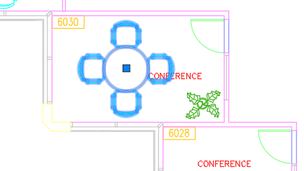
- Click Insert tab > Block Definition panel > Define Attributes.Find
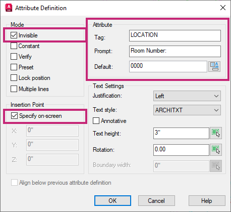
In the Attribute Definition dialog box, match the options and values in the following image:
Under Mode, clear all options except for the Invisible check box.
Under Attributes, enter the following values
- Tag: LOCATION
- Prompt: Room Number:
- Default: 0000
Under Insertion Point, check the Specify On-screen check box.
 Tip:
Tip:Press the F3 key to toggle running object snaps on or off. Turning off running object snap will making placement easier.
Click OK.
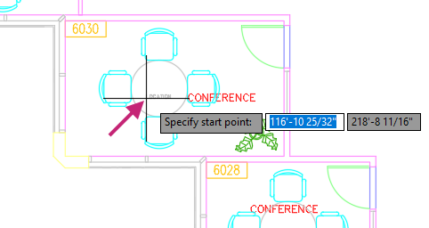
At the Specify start point: prompt, specify a point near the center of the circle (table); exact placement isn't important.
Press Enter to repeat the ATTDEF command.
In the Attribute Definition dialog box, match the options and values in the following image:
In the lower-right, check the Align Below Previous Attribute Definition check box.
Under Attributes, enter the following values
- Tag: ITEMDESC
- Prompt: Item Description:
- Default: Conference Table with 4 Chairs
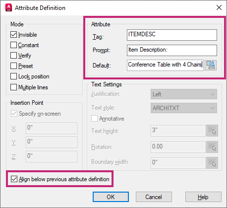
Click OK.
- Click Insert tab > Block Definition panel > Create/Write Block drop-down menu > Create Block.Find
In the Block Definition dialog box, Name text box, type New Conf Table with Chairs.
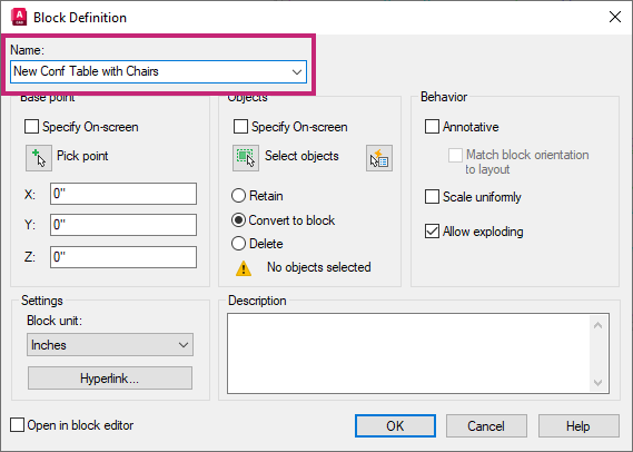
Under Base Point,
Clear the Specify On-Screen check box.
Click Pick Point.
- At the *Specify insertion base point:* prompt, hold down the Shift key and right-click. From the context menu, choose Center.
Specify the center point of the circle.
Under Objects,
Clear the Specify On-Screen check box.
Click the Convert to Block option.
Click Select Objects.

At the Select objects: prompt, select the objects for the block in the following order.
Circle
Array of chairs
LOCATION attribute definition
ITEMDESC attribute definition
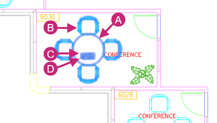
Press Enter to end object selection and return to the Block Definition dialog box.
In the Block Definition dialog box, click OK.
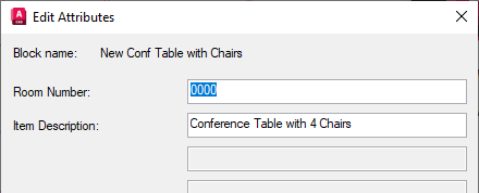
When the block is defined and the Convert to Block option is selected, the selected objects are replaced by a block reference of the new block. This is the same as inserting the block into the drawing, which will result in the automatic displaying of the Edit Attribute dialog box.
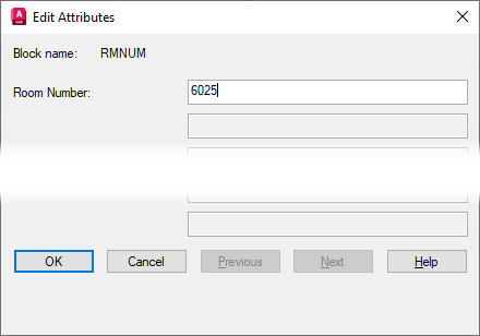
In the Edit Attribute dialog box, click OK to accept the default values.
You could specify new values for the attributes in this dialog box, but you will edit the block's attributes in a few steps.
The attribute values are assigned to the block but are not visible on screen because the attributes were created with the Invisible flag turned on.
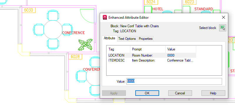
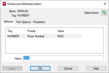
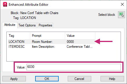
After a block with attributes is inserted, you can edit the values of its attribute. This can be done by doing the following:
Double-click the New Conf Table with Chairs block.
In the Enhanced Attribute Editor dialog box, select the LOCATION tag and replace the current value with 6030.
Click OK to save the changes made.
Now let's replace the other block with conference table and four chairs that doesn't have attributes with the new block.
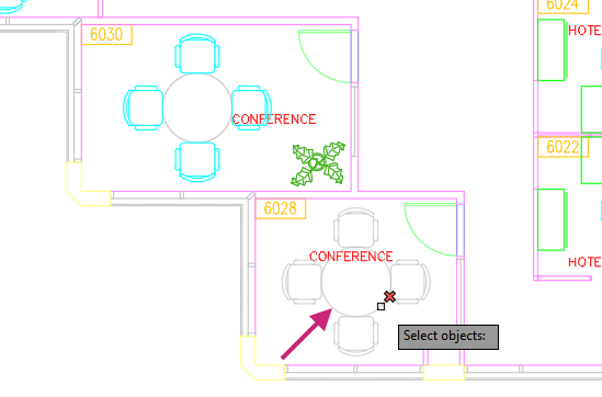
- On the ribbon, click Home tab > Modify panel > Erase.Find
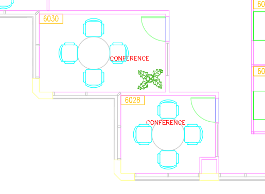
At the Select objects: prompt, select the block with the 4 chairs in the second conference room, labeled 6028, and press Enter.
On the Blocks palette, Current Drawing tab, click New Conf Table with Chairs and specify a point in the Conference Room 6028.
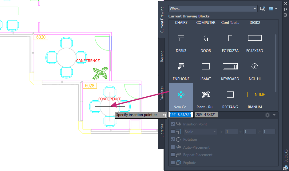
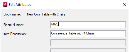
If prompted for a rotation, press Enter to accept the default value.
In the Edit Attribute dialog box, Room Number: text box, replace the default text 0000 with 6028. Click OK.
- On the Quick Access toolbar, click Save.Find
Summary
You learned how to insert blocks into a drawing that represent symbols, parts, detail views, and title blocks. Additionally, you also learned to create your own block definitions in the current drawing with and without attribute definitions.
Related Commands
| Command | Description |
|---|---|
| ADCENTER | Manages and inserts content such as blocks, xrefs, and hatch patterns. |
| ATTDEF | Creates an attribute definition for storing data in a block. |
| BLOCK | Creates a block definition from selected objects. |
| BLOCKSPALETTE | Displays the Blocks palette, which you can use to insert blocks and drawings into the current drawing. |
| EATTEDIT | Edits attributes in a block reference. |