Flange Property Panel Reference
Defines a flange by adding a sheet metal face, a bend, and other parameters to an edge or edge loop on a face.
What's New: 2021, 2025
The Flange Property Panel populates with the default settings from the active Sheet Metal Style. You can override these settings on a per flange basis or on a set of flanges. The property panel provides an optimized workflow.
To learn more about property panels see the following topics:
Access
Ribbon: Sheet Metal tab  Create panel Flange
Flange Property Panel
Specifies the edges, angle, radius, height, Datum from which height is measured, placement, position of the bend relative to the edge, and bend and corner treatments.
Flange Name
A default name is provided, but you can double click the flange name to edit and change it.
 Advanced Settings
The menu at the top-right provides commands relative to the flange workflow.
Active Preset
Displays the named preset in use and provides access to any flange presets you have created. When No Preset displays, property panel fields populate with the last used value.
 Add Preset
Creates a custom preset using the current property panel settings. The preset is available for use when creating sheet metal flanges.
 Preset Settings
Provides control over the presets list and the order in which the presets display.
Input Geometry Group
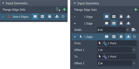
Flange Edge Sets
A collection of one or more flanges that make up a flange feature. The selected edges do not have to be contiguous.
![]() Add Edge Set
Add an edge set to create a flange with different options. Expand an edge set to access the individual edges in the set and their options.
Add Edge Set
Add an edge set to create a flange with different options. Expand an edge set to access the individual edges in the set and their options.
 Edge Selector
By default, edge selection is active when the command is started. To delete an edge selection and reset the selector, click the X at the right end of the row, then select another edge. The selector adds edges to the current set.
Edge Selector
By default, edge selection is active when the command is started. To delete an edge selection and reset the selector, click the X at the right end of the row, then select another edge. The selector adds edges to the current set.
 Edge Loop
Click an edge to select all contiguous, straight edges that form the face. The properties apply to all edges in the Edge set.
Edge Loop
Click an edge to select all contiguous, straight edges that form the face. The properties apply to all edges in the Edge set.
Edge Options
 Edge
Edge
Applies parameters to the full length of the selected edge.
 Width (Extents)
Applies parameters to the selected edge, where the flange width is distributed equally from the edge center.
Width
Specifies the flange width.
 Offset
Enables a flange to start along the selected edge at a specified distance from a selected perpendicular face or plane.
- Offset From: Select a face that is perpendicular to the flange edge.
- Offset Distance: Specifies the distance from the selected offset face.
 Flip Direction: Reverses the offset direction.
 Between
Flange width is defined by the portion of the selected edge lying between the From and To inputs.
- From: The face or plane where the flange begins.
- To: The face or plane where the flange ends.
 Offset
Flange width is defined by offsets from each end of the edge.
- From: The face or plane from which the start offset is measured.
- Offset 1: Specifies the From input offset distance.
- To: The face or plane from which the end offset is measured.
- Offset 2: Specifies the To input offset distance.
Height Extents
Specifies whether you define the height of your flange by a specific Distance or by selecting To geometry.
Distance
Distance includes the flange height value, how the flange height is measured, the flange direction, and the measurement method. The two ways to specify the height measurement are aligned with the flange face or orthogonal to the base face.
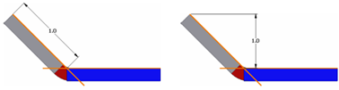
 Aligned (default)
Flange height is measured parallel to the flange angle.
 Orthogonal
Flange height is measured perpendicular to the base plane.
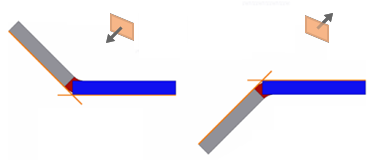
Direction
Used in conjunction with Distance, specifies the side of the base face to which the flange is placed.
![]() Default
Default
The flange is bent toward the side on which the selected edge lies.
 Flipped
The flange is bent toward the side opposite the selected edge.
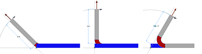
Measurement
Used in conjunction with Distance, defines the measurement method.
![]() Outer Faces
Outer Faces
Measures the flange height from the intersection of the two outer faces.
![]()
 Inner Faces
Measures the flange height from the intersection of the inner faces.
![]()
 Selected Edge
Measures the flange height from the selected edge to the flange face.
Tangent Plane
Measures the flange height parallel to the flange face and tangent to the bend.
![]()
 To
To
Defines the flange height relative to a selected point.
Distance
Select a vertex (point) as the distance input. The flange extends to intersect the point, on the face or plane on which it lies, at the specified angle.
Offset
Specifies the distance from the reference point to where the flange end face.
The To option uses the following method to calculate the termination.
- Offset
- Reference point
- Calculated distance
- Plane parallel to base plane
- Base plane
Angle and Placement
Specifies how the angle value is defined, the placement, and the position of the flange.
Angle (by value)
Defines the angle of the flange relative to the face containing the selected edges. The field accepts numeric entries, formulas, parameters, or measured values.
![]() By Reference
By Reference
Defines the angle of the flange to match, be coplanar with, the selected face or plane.
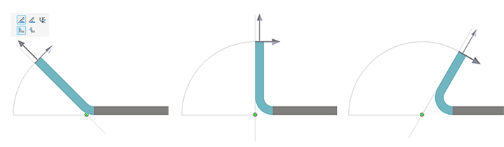
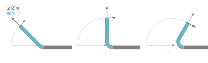
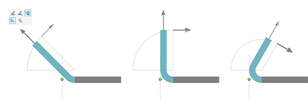
Placement
Specifies how the flange is placed relative to the position of the flange plane.
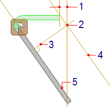
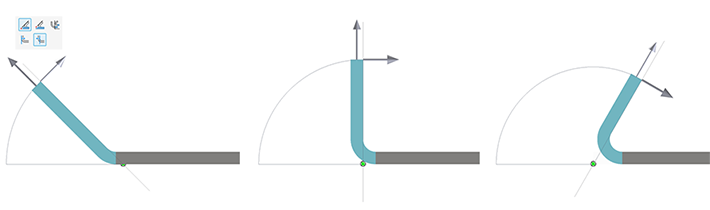
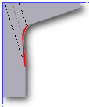
Position
Specifies which side of the flange plane the material is apportioned. The following illustrations demonstrate placement based on the position options.
Outer face through plane
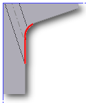
 Plane through partner edge
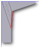
 Plane through selected edge
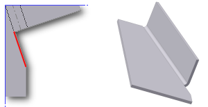
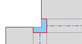
 Plane tangent to or at side face
Inner face through plane
Plane through partner edge
Plane through selected edge
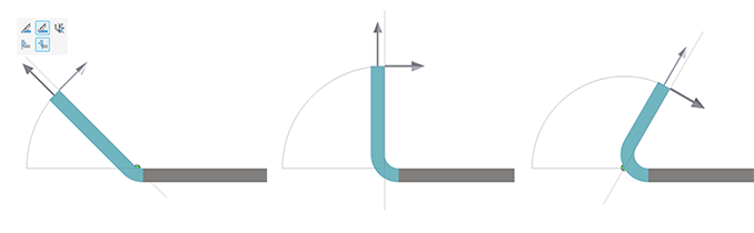
Plane tangent to or at side face
Bend Properties
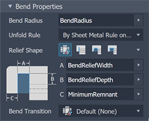
Bend Radius
Defines the radius of the bend between the flange and the face containing the selected edges. The value defaults to the system parameter named BendRadius, which is defined on the Sheet Metal Styles dialog box. The field accepts numeric entries, formulas, parameters, or measured values.
Unfold Rule
Specifies which methods are used to create a flat pattern from the folded sheet metal part. Sheet Metal Unfold rules are defined in the Style Editor. For more information see To Add, Edit, or Sync a Sheet Metal Unfold Rule.
Relief Shape
 Default (by style)
Defined in the Sheet Metal Style. To change the default, modify the style. You can modify the default method by choosing one of the following shapes.
Default (by style)
Defined in the Sheet Metal Style. To change the default, modify the style. You can modify the default method by choosing one of the following shapes.
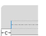
 Tear
Tear
An acceptable bend relief resulting from material failure. It is common when tight bends are required and with certain materials. In the illustration, C represents the size of the material remnant left following the creation of the bend with relief. This parameter defines the value.
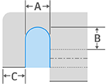
 Round
Round
A bend relief shape defined by a cut ending with a semicircle. It is often produced using laser cutting technology. In the following illustration, A indicates the bend relief width (diameter), B indicates the bend relief depth beyond the deformation zone to the tangent point of the diameter, and C represents the size of the material remnant left following the creation of the bend with relief. Each of these parameters define the bend relief defaults.
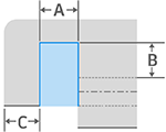
 Straight
A bend relief shape defined by square corners. It is common in manual shop situations and often produced by a saw kerf. In the following illustration, A indicates the bend relief width, B indicates the bend relief depth beyond the deformation zone, and C represents the size of the material remnant left following the creation of the bend with relief. Each of these parameters define the bend relief defaults.
Bend Transition
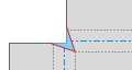
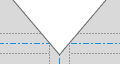
Defines the condition that shows in the flat pattern of the bend. The folded model shows either the transition type of None (for all transition types except Trim), or the type Trim if that is the selected type. The following images show the transition types for this folded model.
![]() None
None
Depending on the geometry, results in a spline between the edges of the two faces meeting at the selected bend.
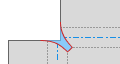
 Intersection
Results in a straight line from the edge of the bend zone that intersects the edge of the bent feature. In the following illustration, the portion of the flat pattern showing this transition type is illustrated for the folded model shown previously.
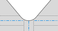
 Straight Line
Results in a straight line from the edge of the bend zone that intersects the edge of the bent feature. In the following illustration, the portion of the flat pattern showing this transition type is illustrated for the folded model shown previously.
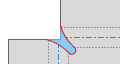
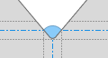
![]() Arc
Arc
Results in a straight line from the edge of the bend zone that intersects the edge of the bent feature. In the following illustration, the portion of the flat pattern showing this transition type is illustrated for the folded model shown previously.
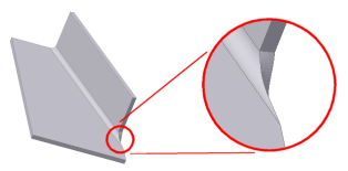
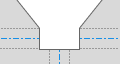
 Trim to Bend
This type of transition is displayed in the folded model and results in a cut to the bend zone perpendicular to the bent feature. In the following illustration (left), the portion of the flat pattern showing this transition type is illustrated for the folded model shown on the right.
Corner Defaults
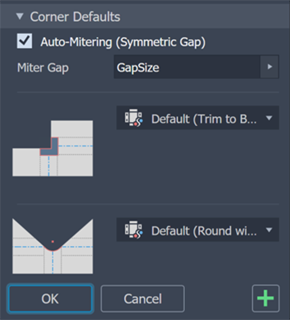
Corner defaults are specified in the Sheet Metal Style. Corner defaults are enabled when more than one flange is being created in the same feature. This enables a smooth workflow where the flange requirements are completely defined in one pass. For individually created flanges that require specific corner treatments, use the Corner Seam command.
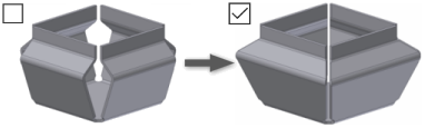
Auto-Mitering
Auto-mitering automatically extends material between adjacent flange edges during creation or edit of at least two flange edges during a single operation where bend angle is greater than 90 degrees. Select the option to have it automatically extend the flanges to create the corner gap.
Miter Gap
Specifies the gap width used when creating mitered corners. The default is GapSize, which is defined in the Sheet Metal Style.
Corner Shape
![]() Default (by style)
Default (by style)
The default is defined in the Sheet Metal Style. To change the default, modify the style.
Round
 Intersection A circular cut out centered on the intersection of the bend lines.
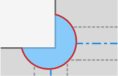
 Tangent A circular cut out tangent to the mitered edges.
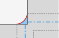
 Vertex A circular cut out whose circumference intersects the shared face tangency point
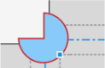
Square
 Intersection A square cut out centered over the intersection of the bend lines.
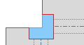
 Vertex A square cut out whose corner intersects the shared face tangency point.
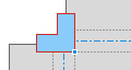
 Tear
Tear
Extends the flange edges to their intersection. No relief, which allows material failure (tearing) across the bend zone in the folded model.

 Trim to Bend
A polygonal cut out bounded by the bending zone lines.
 Linear Weld
A v-shaped cut out defined from the intersection of the inner bend zone lines to the outer bend zone intersection of the line with the flange edges. Minimum relief allows a subsequent weld operation to close the corner.
 Arc Weld
Curves tangent to the flange edges along the outside edge of the bend zone which converge to a flat gap equal to the Miter Gap value. A gap between the flanges that is equidistant along the length of the relief is suitable for subsequent arc welding.
 Laser Weld
Curves tangent to the flange edges along the outside edge of the bend zone which converge to a tangent arc equal to the Miter Gap value. A gap between the flanges that is equidistant along the length of the relief is suitable for subsequent laser welding.
Corner Relief
![]() Default (by style)
Default (by style)
The default is defined in the Sheet Metal Style. To change the default, modify the style.
 No Replacement
Does not replace the geometry as modeled in the flat pattern.
 Intersection
Extends and intersects the flange edges.
 Full Round
Extends the flange edges to their intersection, and then places a fillet tangent to the bend zone tangency lines. Radii are likely larger than what is produced using the Round with Radius option.
 Round with Radius
Extends the flange edges to their intersection, and then places a tangent fillet of the size specified. Radii are likely smaller than what is produced using the Full Round option.
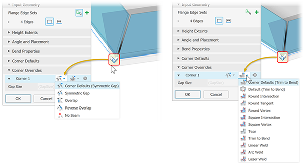
Corner Overrides
Provides overriding relief and shape options for each selected corner when the flange feature is composed of more than one flange.
Corner #
Uniquely identifies corners participating in the selected feature.
Relief Override
Provides corner relief types for the selected corner only. Use the drop down list to select the desired relief condition.
- Corner Defaults: The default is defined in the Sheet Metal Style and displays the related icon. To change the default, modify the style. You can modify the default method by choosing from one of the following conditions.
 Symmetric Gap: Extends the flange face of both edges to create an equidistant gap.
 Overlap: Extends the flange face of the first selected edge to the outer face of the second selected edge.
 Reverse Overlap: Extends the flange face of the second selected edge to the outer face of the first selected edge.
 No Seam
Shape Override
Provides corner shape types for the selected corner only. Select the desired shape from the drop down list. The corner shape list is outlined above.
![]() Gap Size
Gap Size
Sets the gap size for the selected corner. Uses the default size defined in the sheet metal style. Click the icon on the right to override the default.
![]() Relief Size
Relief Size
Sets the relief size for the selected corner. Uses the default size defined in the sheet metal style. Click the icon on the right to override the default.