To Create Coils
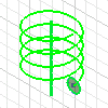
Use coil features to make compression springs or threads on a cylinder.
What's New: 2024.2
The Coil command uses a property panel to define the feature. If you are not familiar with Inventor property panels, see About Property Panels
to learn about the workflow, behaviors, and advanced options, such as the panel menu and advanced settings. Keep in mind the selections you make in a section, determine the options presented in the next section, as you work from top to bottom in the property panel.
Presets can be created for commonly used coil features. To learn more about presets see To Work with Presets.
The processes for creating a spring and creating threads differs. Both processes are considered in the following task descriptions.
Create a Coil Spring

Click 3D Model tab
 Create panel
  Coil
Coil  .
.Without an existing sketch
Select a part face or workplane for the sketch.
Note: If the part is new, Inventor displays the default workplanes. Choose one or create a new one to use for the sketch.Sketch a profile the represents the cross-section of the coil feature.
Use the Line command or Work Axis command to create an axis of revolution for the coil. You can also use one of the Origin axes. It can be at any orientation but cannot intersect the profile.
In the ribbon, click Finish Sketch. The Coil property panel displays.
With an existing sketch
Note: The sketch must have a profile representing the coil cross-section and an axis of revolution - use a line or work axis.- If there is a single sketch, the profile is automatically selected. If the sketch also contains one line that is set to Centerline style
 , it is selected as the axis and a coil preview displays. Otherwise, you must select the line you want to use as an axis.
 - If there are multiple visible sketches, you will be prompted to select the appropriate one.
- If there is a single sketch, the profile is automatically selected. If the sketch also contains one line that is set to Centerline style
In the Coil property panel, specify the Output type:
 Solid. Creates a solid feature from an open or closed section.
 Surface. Creates a surface feature from an open or closed section. Can be a construction surface on which other features terminate, or as a split tool to create a split part.
In Input Geometry select the profile representing the coil feature cross-section. Based on the above, the profile may already be selected.
Profiles. Select one or more profiles to create the coil body.
Axis. Click the axis of revolution. You can use the Flip option to reverse the direction of the feature.
Note: The Flip option reverses the axis direction. Use Rotation to adjust the feature if needed.In Behavior specify the parameters for the displayed fields, which may include:
- Method: choose from Pitch and Revolution , Revolution and Height, or Pitch and Height.
- Pitch: Specifies the elevation gain for each revolution of the helix.
- Revolution: Specifies the number of revolutions for the coil. Must be greater than zero, but can include a fraction (for example, 1.5 turns). The number of revolutions includes any end conditions that you specify.
- Height: Specifies the height of the coil from the center of the profile at the start to the center of the profile at the end.
- Taper: Specifies the taper angle, if needed, for all coil types except Spiral.
Rotation
 Left
Left Right
Right
Choose the Start transition methods and angles:
Note: To have a coil with natural ends, no transition, unselect Close Start and Close End.- Close Start. Specifies the start end type.
- Flat Angle. Create a transition in the pitch of the coil. For example, enter a Transition Angle and then a Flat Angle (up to 360 degrees), to stand upright on a flat surface.
- Transition Angle. The distance (in degrees) over which the coil achieves the start transition (normally less than one revolution). The example shows the top with a natural end and the bottom end with a one-quarter turn transition (90 degrees), and no flat angle.

- Close End
- Flat Angle. The distance (in degrees) the coil extends after transition with no pitch (flat). Provides transition from the end of the revolved coil to a flattened end. The example shows the same coil as the Transition angle shown previously, but with a half-turn (180 degree) flat angle.

- Transition Angle. The distance (in degrees) over which the coil achieves the end transition (normally less than one revolution).
- Flat Angle. The distance (in degrees) the coil extends after transition with no pitch (flat). Provides transition from the end of the revolved coil to a flattened end. The example shows the same coil as the Transition angle shown previously, but with a half-turn (180 degree) flat angle.
- Close Start. Specifies the start end type.
Specify Output. For base features the Output parameters are not displayed because there is only applicable choice, join. When one or more bodies exist in the model, you have the option to Join, Cut, Intersect, or create a new solid as needed.
Boolean
 Join. Adds the volume created by the lofted feature to another feature or body.
 Cut. Removes the volume created by the lofted feature from another feature or body.
 Intersect. Creates a feature from the shared volume of the lofted feature and another feature. Deletes material that is not included in the shared volume.
 New Solid. Creates a solid body. If the loft is the first solid feature in a part file, this is the only option. Select to create a body in a part file with existing solid bodies. Each body is an independent collection of features, separate from other bodies. A body can share features with other bodies. If desired, rename the body.
Solids
- If there are multiple solid bodies, click the Solid selector and select the participating body.
Click OK or Apply
 to continue creating additional coil features.Note: Use the Advanced Setting option Keep sketch visible on (+) to continue to use the path sketch for additional coil features.
Create Threads on a Cylinder

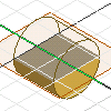
To create threads, you first create a cylinder, work plane, and work axis to position the thread profile, then you create and position the profile for the threads, and finally you cut the threads.
Create a cylinder and work features to position threads. Place the work features on the cylinder center, perpendicular to the cylinder end.

- Create a profile using commands on the Sketch tab.
- On the 3D Model tab, Create panel, click Extrude
 to extrude the profile into a cylinder.
 - In the browser, click the Origin icon, select the default work planes, right-click, and click Show.
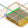
Create and position a profile for the threads. Create a sketch plane on the work plane, perpendicular to the end of the cylinder.

- Sketch the thread profile.
- Project the silhouette of the cylinder, the top or bottom edge of the cylinder, and the work axis to the sketch plane.
- To position the profile shape relative to the cylinder, constrain it, and add dimensions. Usually the profile is offset from the end of the cylinder so that threads are positioned correctly at the top of the cylinder.
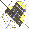
Create threads. To begin, sketch a profile that represents the cross section of the coil feature. Then, use the Line command or the Work Axis command to create an axis of revolution for the coil.

- Click 3D Model tab
 Create panel
  Coil
Coil  .
. - For Input Geometry, specify the profile and the axis of revolution.
- Specify the Behavior: Method and its parameters, Rotation, and end treatments.
- Under Output > Boolean, select Cut.
- Click OK or Apply if you want to continue creating coils.
- Click 3D Model tab