Exercise 2
Previous: Chapter 8 | Next: Chapter 9
This exercise teaches how to assign materials. You will also learn how to create a custom material and save it to a custom material database.
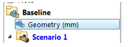
Ensure units are set to mm on the Geometry branch of the Design Study Bar.
Autodesk® Inventor, PTC Creo, and Solidworks:
Units should already be mm. No action required.
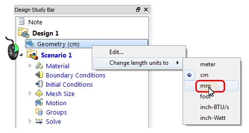
UGNX:
Right click on the Geometry branch.
Select mm.
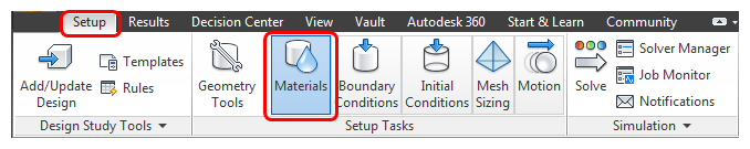
Click Materials on the Setup tab:
Left click on the Car Body. Click the Edit button in the context toolbar.
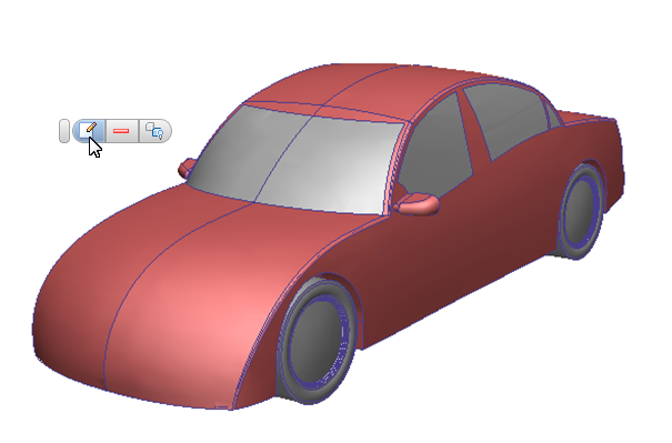
Type = Solid, Name = Steel, click Apply.
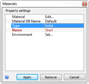 Note: Fields in the right column become menus when you click on them.
Hide the car body.
Note: To hide objects, right click on the object and select Hide, or press the Ctrl key and middle click on the object.Select the internal cabin air volume, and click the Edit button on the context toolbar.
Type = Fluid, Name = Air, click Apply.
Hide the air part just assigned.
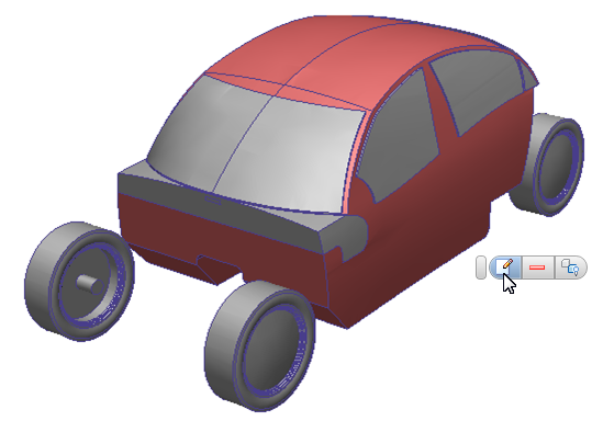
Select the four wheels and click the Edit button from the context toolbar.
Type = Solid, Name = Silicon Rubber, click Apply.

Hide the wheels.
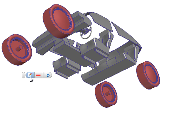
Select the rear seat, the two front seats, and the console. Click the Edit button from the context toolbar.
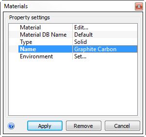
Type = Solid, Name = Graphite Carbon. Click Edit on the Material line.
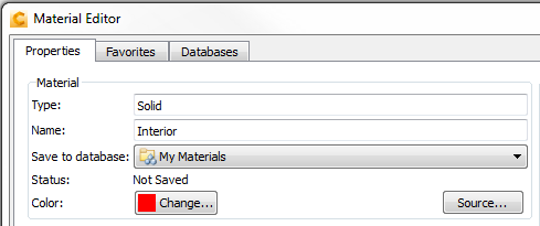
On the Material Editor, Name = Interior, Save to database = My Materials.
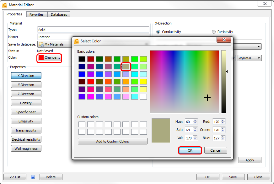
Click Color: Change. In the Select Color dialog, select a tan color, and click OK.
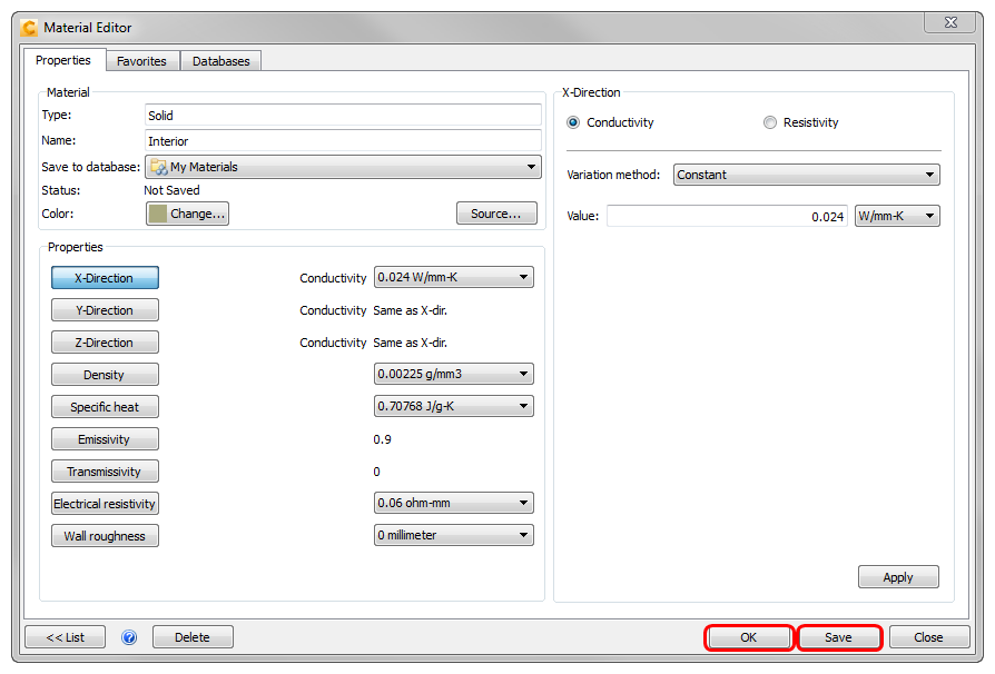
 Note: We could also have modified physical properties in the Material Editor, if appropriate.
To save the new material to your custom material database, click Save and OK in the Material Editor.
To apply the "Interior" material, click Apply on the Material quick edit dialog.
Hide the seats and console.
Select the three air volumes in the ducts and click the Edit button from the context toolbar.
 Note: The upper and lower volumes in this image were created automatically by Autodesk® CFD. The center volume is a part from the CAD model. We'll use this part when we assign the mesh distribution to demonstrate mesh controls.
Material DB Name = Default. Type = Fluid, Name = Air. Click Apply.
Hide the air parts just assigned.
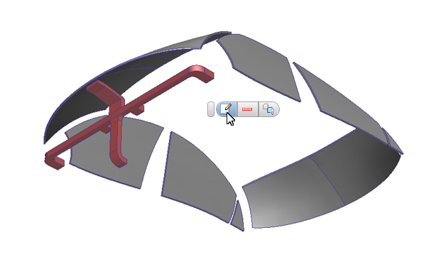
Hold the left mouse button and drag a rectangle around the remaining parts.
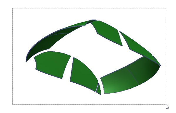
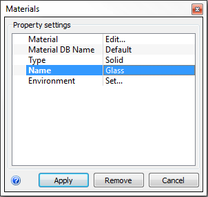
Left click off the model, and click the Edit icon in the context toolbar.
Type = Solid, Name = Glass, click Apply.
Right-click off the model, and click Show all.
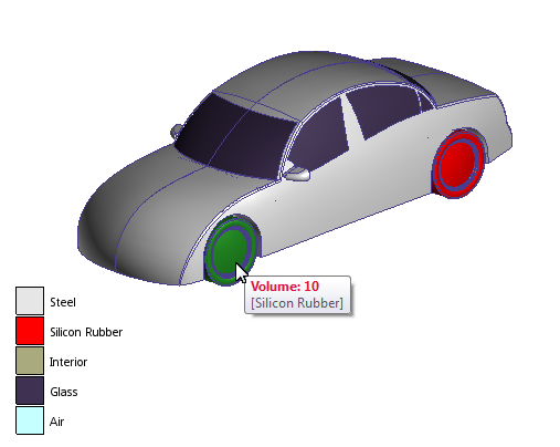
Confirm that all parts are assigned the proper material:
Compare part colors with the legend in the lower left corner.
Alternatively, hover your mouse over parts to see the assigned material.
If any part is incorrectly assigned or “unassigned”, please correct it now.
End of Exercise.