Observe Geometry Issues in CFD
In this section we will Launch into Autodesk® CFD and look at the 4 issues that we found with the Model Assessment Toolkit.
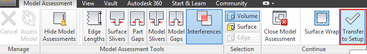
Click Transfer to Setup in the ribbon.
Close the Geometry Tools dialog if it comes up.
Note: Notice in the message window that the fluid volume inside the housing wasn't generated: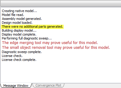
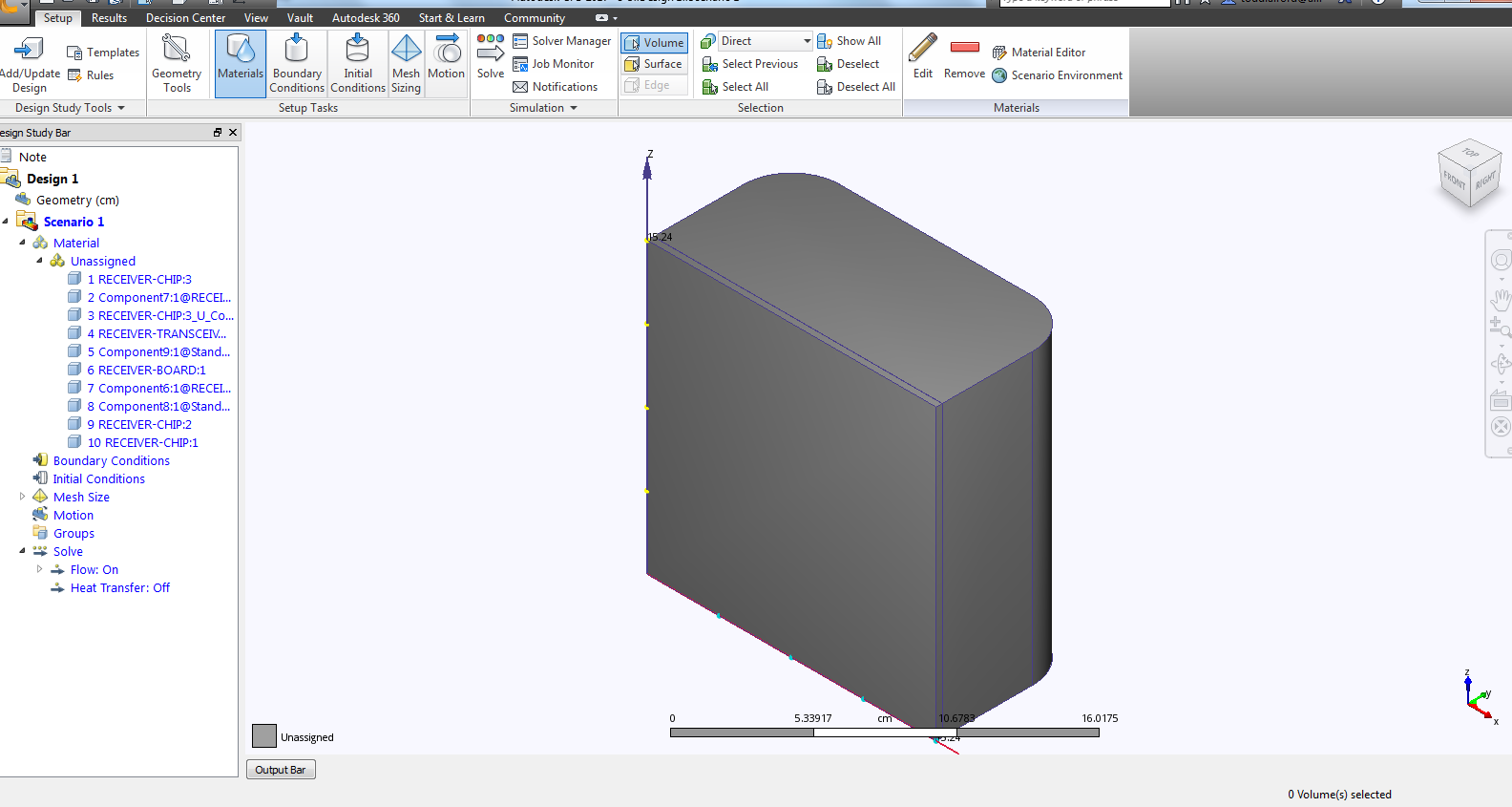
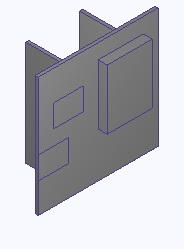
Click on the top of the Output Bar to hide the message window. The screen should then appear like this:
Place the curser over the bottom plate of the housing. Then hold down the control button and also hold down the middle mouse button.
Note: While the buttons are being held down, the surfaces where parts contact each other will be highlighted green. Notice that there is no air volume on the inside, and the bottom of the housing doesn't touch the top housing part. This confirms what we observed in the Model Gaps of the Model Assessment tool.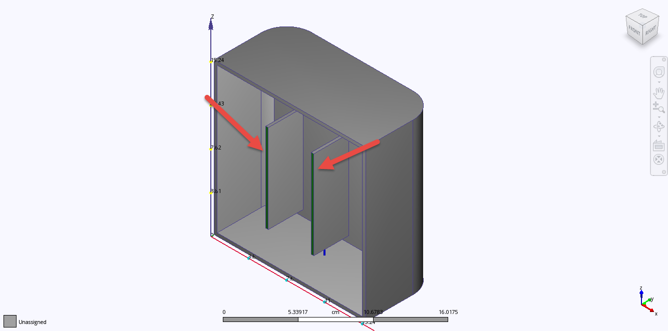
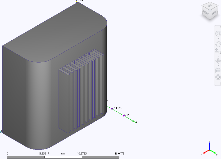
Rotate the model using the top right corner of the view cube

The model orientation should be as follows:
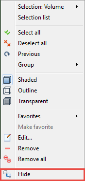
Right-click on the housing and select Hide from the context menu:
Click on the right side of the Design Study Bar and pull the window to see the full part names, as shown:
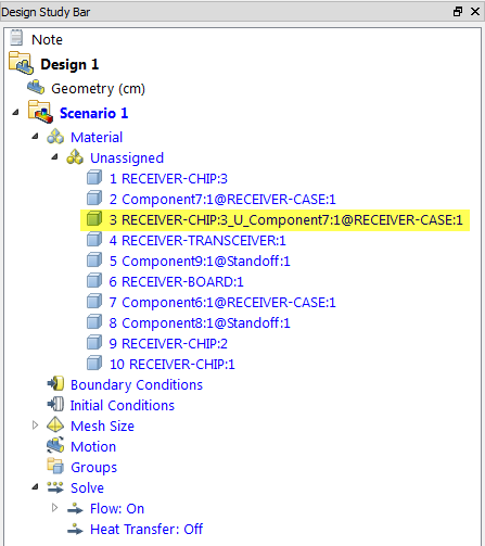 Note: Notice the part name of Volume 3 is formatted as the name of the first and second volumes with _U_ between them. That naming format shows that it is a volume created from an intersection.
Select Volume 3 in the design study bar.
Note: It is typically not intuitive what materials should be assigned to a part created by an interference. Meshing errors can also occur due to these small volumes.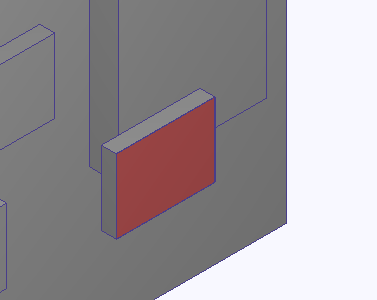
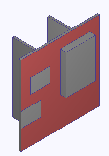
Hide all of the small chips using your preferred method. The model will be similar to the following image:
In the selection section of the ribbon, select Surface.
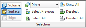
Select the largest surface on the top of the board.
Scroll the mouse wheel to zoom in to the imprint left by the lower left chip.
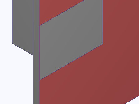 Note: The imprint created during the launch creates a small sliver on a large surface.
Rotate to the top view by clicking on the top surface of the view cube
 .
.Scroll the mouse wheel to zoom in towards the large chip.
 Note: The small chamfer on the chip is both a sliver surface and a small gap that the fluid will occupy.
Close the program and hit Save.