Simulation Ready Geometry in CFD
In this section we will observe the geometry with the 4 issues removed from the geometry.
Observe the Message window.
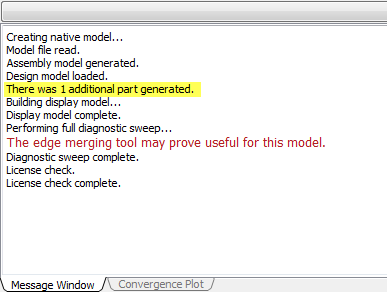 Note: There is a coincidental mating of housing parts so that an additional part is generated.
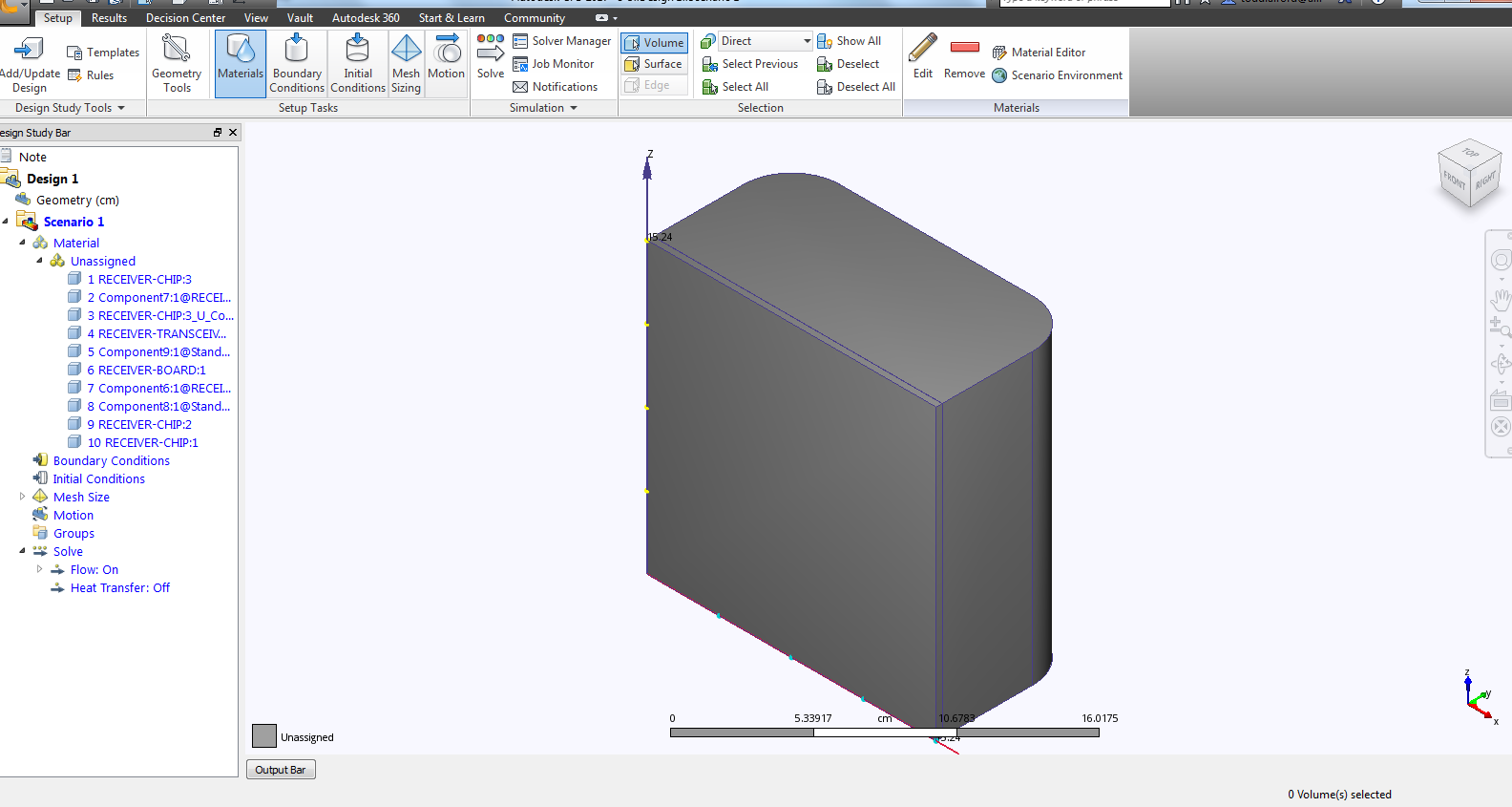
Click on the top of the Output Bar to hide the message window. The screen should then appear as follows:
Hide the bottom plate of the housing using your preferred method (right-click or Ctrl+MMB).
Select the fluid volume that was created.
Note: 10 Volume is highlighted in the design study bar, parts created to fill gaps within Autodesk® CFD will follow the same naming convention.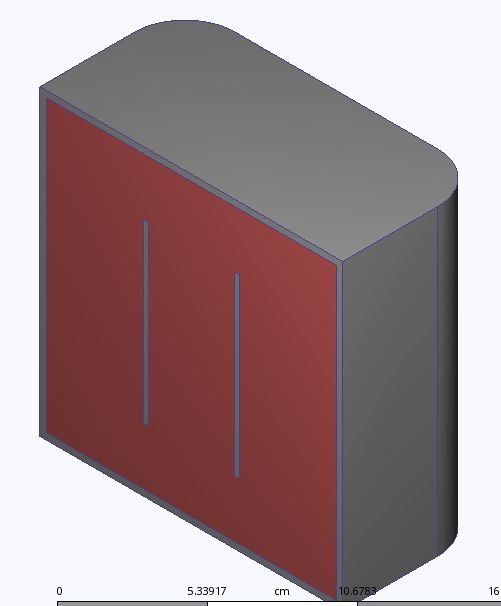 Note: In the Design Study bar the partname_U_partname is now missing because there are no interferences in the current model.
Rotate the model using the top right corner of the view cube 
The model orientation should be as follows:
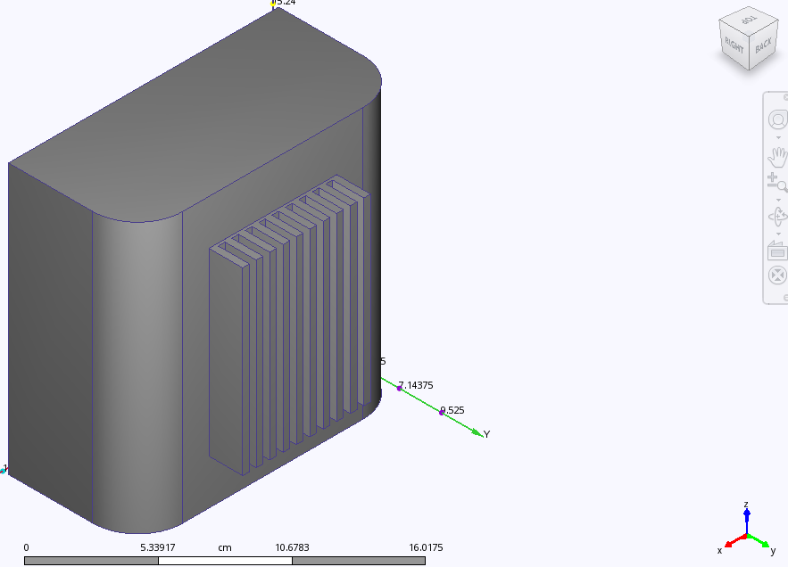
Hide the top housing and fluid volume using your preferred method (right-click or Ctrl+MMB). The model should appear similar to:
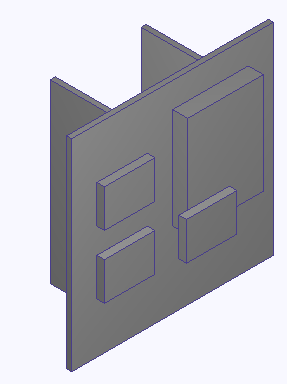 Note: The Chip has been moved from the edge of the board, and the chamfer has been removed. This model is simulation ready. To setup and run this model Close Autodesk® CFD and proceed to Tutorial: Internal Natural Convection in a Telecommunications Module.