Note: Before making a start on this tutorial, it is important to ensure that the units of measurements shown in
InfoWorks ICM displays are set to metric. For this, select
Options from the
Tools menu and click on the
Units tab. Ensure that default units are set to
Metric (Native).
We will start this tutorial by importing a gridded ground model.
- In the Explorer window, within your database, right-click on the database and select New | Model Group from the popup menu
- In the New Name - Model Group dialog, type in a name for the new model group (e.g. Model Group). Click on OK.
- Right-click on the newly created Model Group in the Explorer window and create a brand new InfoWorks network by selecting New InfoWorks | InfoWorks Network from the popup menu.
- Enter a name for the network in the New name - InfoWorks Network dialog (e.g. River example). Click on OK.
- Open the River Example network on the GeoPlan by double-clicking it or dragging it and dropping it onto the InfoWorks ICM background. There are currently no objects in the network.
- Import the supplied LiDAR data to create a Gridded Ground Model:
- In the Explorer Window, right-click on the Model Group you have created in point 2 and select Import InfoWorks | Ground model grid... | From ground model grid files... or Import InfoWorks | Ground model grid... | From ground model folder... from the popup menu.
- This displays a File Open dialog.
- Browse to the location of the Example Data Directory where the tutorial files have been installed.
- Select all the provided asc files inside the Ground Model folder or the Ground Model folder itself depending on the option you have chosen in a and click Open.
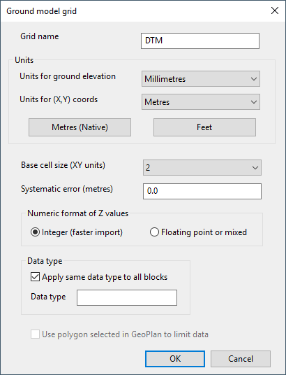
- This displays the Ground Model (Grid) Import Dialog.
- Give the name DTM to the Ground Model (to be typed in Ground Model Grid box)
- Use the supplied defaults.
- Click on OK to import the files and generate the ground model
- Drop the DTM Ground Model object onto the network that should still be open in the GeoPlan.
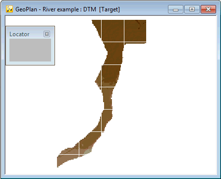
- In order to visualise the Ground Model in the GeoPlan, right-hand click on the GeoPlan and select the Zoom to ground model option. The ground model is displayed with the default theme.
- Let us customise the ground model theme to illustrate how themes can be used in
InfoWorks ICM. Please refer to the
Displaying a Ground Model on the GeoPlan and the
Layer Theme Editor topics for further information.
- Right-hand click on the GeoPlan and select Properties & themes from the context menu.
- Scroll down to the Ground Model object layer.
- Click on the Edit button of the Theme column for the Ground Model object.
- The Layer Theme Editor is displayed.
- Click on the Colour theme on the Sub Theme Manager Pane (left hand-side).
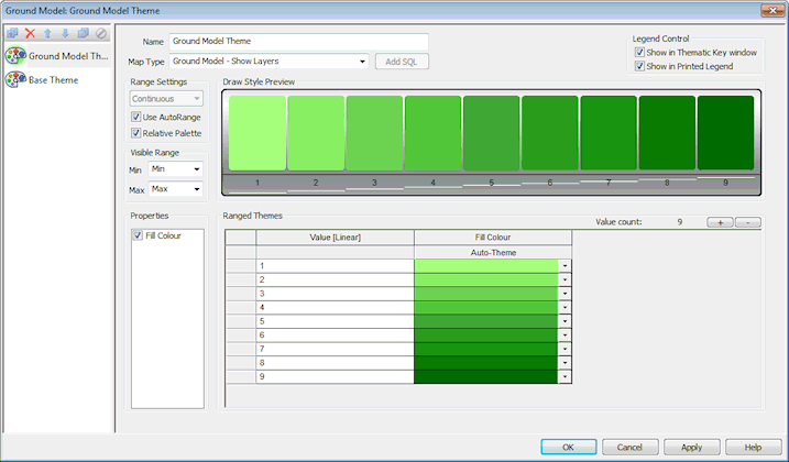
- Replace the Colour theme by a theme using the settings shown below:
- Follow the following steps to set up the customised ground model theme and obtain a Layer Theme Editor similar to the one presented in the screenshot above:
- Type Ground Model Theme in the Name box.
- Select Ground Model - Show Layers in the Map Type dropdown list.
- Add 4 more values to the range (there are currently 5 ranged themes) by clicking four times on the + button located to the right-handside of the Ranged Themes section.
- Leave the Range Settings set to Continuous as we want the Ground Model to be displayed based on a series of ranges of elevation.
- Click on Relative Palette (values change to 1, 2, 3, 4, 5, 6, 7, 8 and 9). This means that the selected set of colours will be applied in the Fill Colour column of the Ranged Themes grid to the part of the Ground Model currently being viewed on the GeoPlan and that values will be automatically re-scaled when the GeoPlan zoom is changed.
- Select a green colour in the Fill colour column for the low and high end of elevations (light green for 1, dark green for 9) by clicking on the corresponding down arrow buttons and selecting a colour in the palette.
- Click repeatedly on Auto-Theme (underneath the Fill Colour header) until you get a smooth sequence of green colour going from light to dark green.
- Click on OK on the Layer Theme Editor to save your changes. The editor closes.
- Back in the Layers and Themes tab of the GeoPlan Properties dialog, you can click on OK, Apply or Save. We are going to save the current GeoPlan properties as a default theme for all networks of a similar type.
- The Network editing properties - save options dialog is displayed.
- Select the Save as default for all networks of this type option and click on OK.
- Click on OK on the Layers and Themes tab of the GeoPlan Properties dialog to close it.
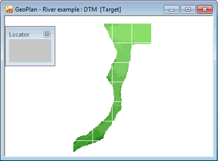
- The ground model is displayed on the GeoPlan with the theme you have just configured.
We can now build the river reach from cross section and river centre line data.
 Back to River Tutorial
main page.
Back to River Tutorial
main page.