 Back to
previous stage.
Back to
previous stage.
The first step in building a river reach is to import cross sectional survey data. Then, once imported, these sections will need a river centre line.
This topic covers the import of cross section survey data and river centre line using CSV files and the Open Data Import Centre respectively, as an illustration of the many sources of data that can be imported into InfoWorks ICM:
- Ensure that the River example network and the DTM ground model are both open on the GeoPlan.
- Select the Update from CSV files… option from the Network menu, then the Import option.
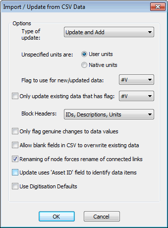
- The Import / Update from CSV Data dialog is displayed.
- Ensure Update and Add is selected in the Type of Update dropdown list and that IDs, Descriptions, Units is selected in the Block Headers dropdown list.
- Click OK.
- In the Select one of more CSV Files to import dialog, browse for the provided cross_section.csv file in the Example Data Directory where tutorial files have been installed. Select the file.
- Click Open.
- Once the data is imported, click on the Cancel button of the Select one of more CSV Files to import dialog to close it.
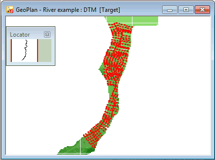
- The imported cross sections are visible on the GeoPlan and a Results of CSV Update message is displayed, giving details on the import.
- Close the Results of CSV Update message.
- You will notice that the River example network icon in the Explorer window is now displayed with a red symbol in the bottom right hand corner, indicating that the network has local changes that have not yet been committed to the database.
- Use the
Properties Tool (
 ) from the
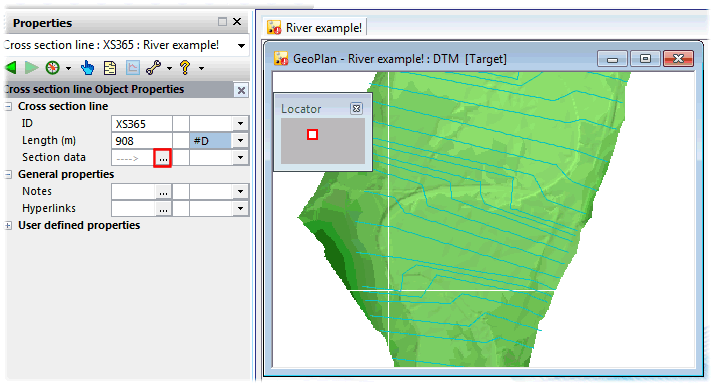
GeoPlan Tools toolbar, look at the data associated with one or more of the Survey Sections.
) from the
GeoPlan Tools toolbar, look at the data associated with one or more of the Survey Sections.
- To view the section data, click on the
 button adjacent to the
Section data section of the cross section line Property Sheet.
button adjacent to the
Section data section of the cross section line Property Sheet.
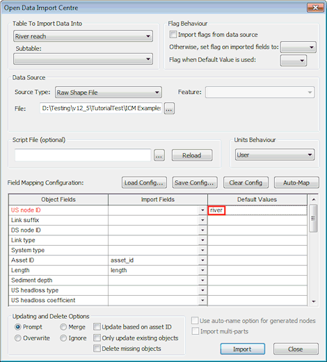
- We are now going to import an ESRI Raw Shape file data for the river centre line. Display the Open Data Import Centre by selecting Network, then Import, then Open Data Import Centre.
- Select River reach in the Table to Import Data Into dropdown list.
- Select Raw Shape File in the Source Type dropdown list.
- Click on the
 button close to the
File box.
button close to the
File box.
- This displays a standard Windows Open dialog. Browse to the location of the tutorial files in the Example Data Directory. Select the provided river_centre_line.shp file and click on Open.
- Type in river in the Default Values cell corresponding to US node ID.
- On the Open Data Import Centre dialog, click on Auto-Map.
- Click Import.
- Click OK on the message that is displayed letting you know that one object has been successfully imported.
- Close the Open Data Import Centre by clicking on the Close button.
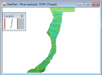
- The imported river centre line is visible in the GeoPlan.
- Every time a version-controlled item, such as the network, has been changed, it is good practice to commit the changes. Changes are stored in your own local copy of the network (in your
Local Working Folder directory) and must be committed to the database so that they become available to other users. Also, committing changes on a regular basis allows you to discard all the changes you have made since the last time you committed the network to the database.
- In the Explorer window, right-hand click on the River example network and select Commit changes to database.
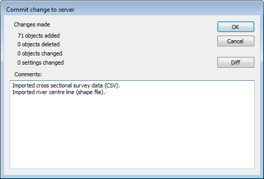
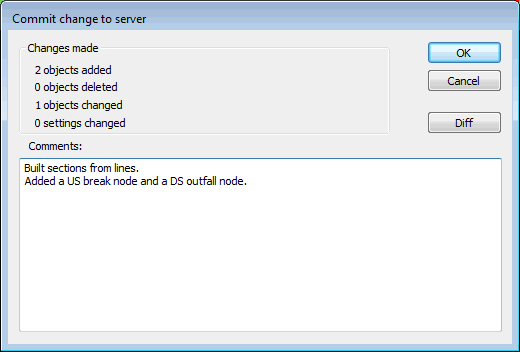
- The Commit change to server dialog is displayed.
- Type in any notes as appropriate.
- Click OK to commit the changes and close the dialog.
- If a message is displayed asking you if you wish to validate the network at the same time as you are committing your changes, click on No for now. We will validate the network at a later stage.
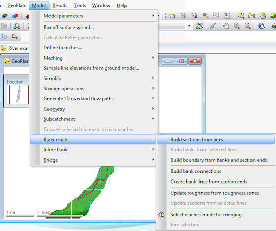
- The river centre line and the cross sections are prerequisites for river reach building therefore, the next stage is to combine them in order to make them physical assets in the network. Select the river centre line in the GeoPlan by using the
Selection tool (
 ) of the
GeoPlan Tools toolbar and select
River reach, then
Build sections from lines from the
Model menu.
) of the
GeoPlan Tools toolbar and select
River reach, then
Build sections from lines from the
Model menu.
- Once the reach has been built, you will notice that there are now dotted lines, which represent the sections and banks within the river reach (cross section lines remain solid).
Sections and banks are displayed according to settings available in the Elements tab of the GeoPlan Properties dialog (right-click in GeoPlan, select Properties & Themes, click on the Elements tab).
- Deselect all the selected objects on the GeoPlan by using the
Clear Selection button (
 ) on the
Selection toolbar.
) on the
Selection toolbar.
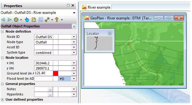
- The final step in creating a complete river reach is to define its upstream and downstream limits by adding an upstream and a downstream node. At the upstream end of the river reach we are going to add a break node (as shown below) and at the downstream end an outfall with a ground level of 121.40mAD.
- For this, set the
New Object type to
node and click on the
New Object tool (
 ) of the
GeoPlan Tools toolbar and add a Break node at the US end of the reach (South) and an Outfall Node at the DS end (North).
) of the
GeoPlan Tools toolbar and add a Break node at the US end of the reach (South) and an Outfall Node at the DS end (North).
- In the
Create New Node dialog, use the following parameters and click on
OK.
Field
US node
DS node
ID
Break US Outfall DS Type
Break
Outfall
- Once you digitise a new node, its Property Sheet is automatically displayed in the Object Properties Window. Ensure you enter a ground level of 121.40 mAD at the Downstream Outfall. You can, if you wish, enter a ground level of 136.720 mAD at the Upstream Break Node although break nodes do not necessarily need to have an assigned ground level.
Note: Make sure that the cross hairs coincide with the sections. You may want to zoom onto the areas of interest in order to optimise node location.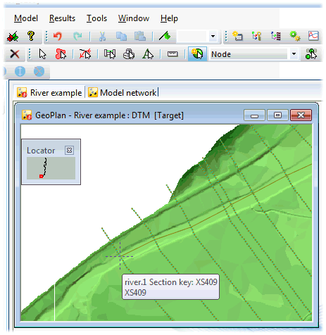
- For this, set the
New Object type to
node and click on the
New Object tool (
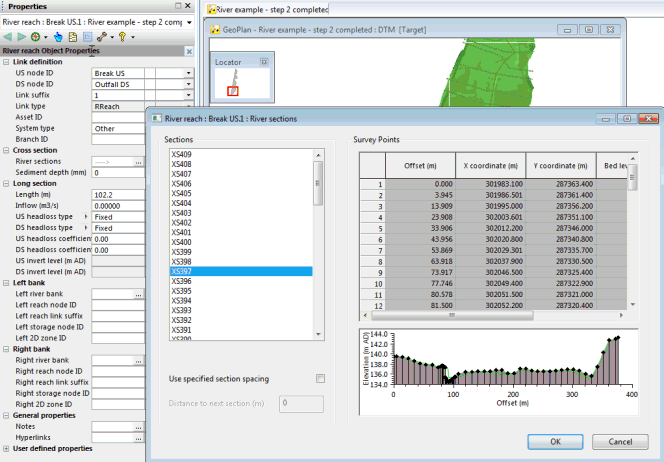
- The river reach is now complete. Open the property sheet for the river reach by selecting the
Properties button () on the
GeoPlan Tools toolbar and selecting the river reach in the GeoPlan. Look at all the cross sections by clicking the
button adjacent to the
River sections section. As you scroll up and down each cross section will be drawn in turn.
- Click OK on the River sections dialog once you have finished looking at the data. This closes the River sections dialog.
- Let us commit the network again. Follow steps similar to the ones described in bullet point 24.
It is now necessary to define river banks.
 Back to River Tutorial
main page.
Back to River Tutorial
main page.