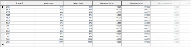
The Pipe network catalog defines the pipe shapes, sizes, and associated design limits available to the Network design tool.
Each catalog entry represents a candidate pipe configuration that may be evaluated during pipe sizing. Only entries contained in the active Pipe network catalog are considered during the design process.
Purpose
The Pipe network catalog:
- Defines the set of pipe geometries available for selection
- Specifies geometric and hydraulic limits for each pipe size
- Supplies constraint values used during slope-bound calculations
- Determines which pipe sizes are eligible during candidate evaluation
If a pipe size is not included in the catalog, it cannot be selected by Network design.
Note: Pipe network catalog objects are database-wide and may be reused across multiple networks.
Catalog structure and units
Each catalog entry defines geometric dimensions and constraint values used during candidate evaluation.
The following attributes may be specified (units follow project settings):
| Attribute | Units | Description |
|
Shape ID |
- |
Cross-sectional shape (e.g. circular, rectangular) |
|
Width |
mm * |
Pipe width |
|
Height |
mm * |
Pipe height |
|
Minimum slope |
m/m ** |
Smallest allowable longitudinal slope |
|
Maximum slope |
m/m ** |
Largest allowable longitudinal slope |
|
Minimum velocity |
m/s *** |
Minimum allowable velocity at peak flow |
|
Maximum velocity |
m/s *** |
Maximum allowable velocity at peak flow |
|
Maximum percentage full |
% |
Maximum allowable full-flow condition |
|
Minimum cover depth |
m * |
Minimum burial depth |
|
Maximum cover depth |
m * |
Maximum burial depth |
| Relaxed minimum slope |
m/m ** |
Smallest allowable longitudinal slope used when the slope constraint is relaxed. |
| Relaxed maximum slope |
m/m ** |
Largest allowable longitudinal slope used when the slope constraint is relaxed. |
| Relaxed minimum velocity |
m/s *** |
Minimum allowable velocity used when the velocity constraint is relaxed. |
| Relaxed maximum velocity |
m/s *** |
Maximum allowable velocity used when the velocity constraint is relaxed. |
| Relaxed minimum cover depth |
m * |
Minimum burial depth used when the cover depth constraint is relaxed. |
| Relaxed maximum cover depth |
m * |
Maximum burial depth used when the cover depth constraint is relaxed. |
| Relaxed maximum percentage full |
% |
Maximum percentage full condition used when the percentage full constraint is relaxed. |
* or project length units | ** or project slope units | *** or project velocity units
These limits, including relaxed limits where specified, are applied only when the corresponding constraint type is enabled in Design considerations (see Design constraints).
Relaxed values extend the permitted range used during fallback design. To prevent a constraint from being relaxed, set the relaxed value to match the corresponding main constraint value.
Maximum percentage full is evaluated as a depth ratio (d/D) at the calculated peak design flow.
During candidate evaluation, velocity calculations use the flow depth derived from the maximum percentage full constraint which is defined in the Pipe network catalog for the candidate cross-section. The velocity is calculated using either Manning's equation or the Colebrook-White equation, depending on the roughness model defined for the conduit (see Network design).
Cover depth is calculated using the node ground level and the pipe soffit only. Ground model data is not used during Network design.
How catalog entries are evaluated
During Network design, each pipe is evaluated against entries in the active Pipe network catalog. Each entry represents a candidate pipe size and associated limits.
Candidate evaluation follows the standard Network design process (see How Network design works).
Creating and editing a Pipe network catalog
The Pipe network catalog is defined as a tree object containing a table of pipe entries.
To use a catalog in Network design:
- Select an existing Pipe network catalog or create/import a new tree object.
- Drag the desired Pipe network catalog object into the Network design window.
- Run the design process.
Catalog entries may be edited to:
- add or remove pipe sizes and shapes
- modify slope limits and relaxed slope limits
- modify velocity limits and relaxed velocity limits
- modify percentage full limits and relaxed percentage full limits
- modify cover depth limits and relaxed cover depth limits
Changes to the catalog affect subsequent design runs.
Important considerations
When defining a Pipe network catalog:
- Ensure slope limits are realistic.
- Ensure velocity limits are consistent with design standards.
- Avoid conflicting limits (for example, minimum slope that always violates maximum velocity).
- Confirm that at least one catalog entry can satisfy applicable slope constraints for the expected design flow.
Overly restrictive combinations may result in infeasible pipes.
If the design fails due to lack of feasible candidates, consider:
- reviewing the relaxed constraint values in the Pipe network catalog
- changing the relaxed constraints order in Design constraints
- adjusting Design constraints to allow backdrops
- modifying penalty configuration
- manually designing the failed pipe and continuing the design downstream