Network design (Tech Preview) is an automated preliminary sizing tool for gravity drainage networks.
It determines pipe diameters and invert levels in a dendritic network by estimating peak flows and evaluating candidate pipe configurations against hydraulic, geometric, and connectivity constraints.
Peak flows are calculated either from rainfall intensity derived from an IDF curve (using the Rational Method) or from user-specified design flows, depending on the selected peak flow calculation method. Candidate pipe sizes and associated design limits are defined in a Pipe network catalog, while the Design constraints control the connectivity arrangement, the considerations and the orchestration of the design process.
Network design can be applied to the entire network or to a selection of pipes defined by a Selection list. The selected pipes form the design region. During execution, pipes are processed sequentially in an upstream-to-downstream direction using a deterministic constraint-based design algorithm. Pipes that impact the design and are not included in the selection list are still passed to the design engine for level consideration but are treated as skipped elements from the design.
For each pipe, feasible slope bounds are derived from the active constraints and the governing constraint determining the final slope is identified. Where multiple feasible candidates exist, a weighted penalty system is used to select the preferred solution.
After completion, Network design updates pipe sizes and invert levels in the network and generates a Design report. The report documents evaluated candidates, calculated slope bounds, governing constraints, and the final selected configuration for each pipe.
Intended use
Network design is a preliminary sizing tool used to determine pipe diameters and invert levels based on peak flow assumptions.
It is intended for use during the design phase to satisfy connectivity, depth, velocity and conveyance requirements. The tool evaluates candidate pipes and determines initial sizes and levels that satisfy the defined hydraulic and geometric constraints.
Network design does not consider hydraulic throttling devices (such as orifices, weirs, or pumps) or storage structures during the sizing process. Final designs should be validated and stress tested using dynamic hydraulic simulation to account for attenuation, control structures, throttling effects, and storage behaviour.
Input options
Before running Network design, several inputs must be configured to define design constraints, available pipe sizes, rainfall data, and the portion of the network to be designed.
Inputs include:
- Design constraints
- IDF curve
- IDF curve return period
- Selection list
- Pipe network catalog
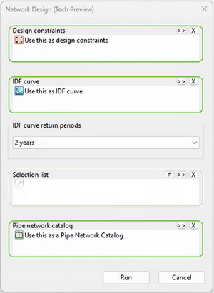
Network design Main Window
Requirements
Before running Network design:
- The network must be an InfoWorks network (see Networks).
- The network must be dendritic (see note below).
- Catchment data must be defined for pipes that contribute to peak flow calculations. The design tool will interact with the following parameters from the subcatchment data fields:
- contributing area
- rational method time of concentration Tc (minutes) (new attribute)
- rational method runoff coefficient (new attribute)
- An IDF curve must exist when the peak flow calculation method is set to 'Rational method' within the Design constraints.
- An IDF Curve return period must be specified when an IDF curve is used.
- A Pipe network catalog must exist.
- A Design constraints object must be configured.
- A Selection list must be defined if only part of the network is to be designed.
Pipes outside the design region are not modified and retain their existing geometry. These pipes provide fixed boundary levels during the design process, and the user can choose to ignore these fixed boundaries in the Design constraints configuration.
How Network design works
Network design processes pipes sequentially in an upstream-to-downstream direction within the selected design region.
For each pipe, the following steps are performed:
- Calculate the design flow at the pipe location using the selected peak flow method.
- Evaluate candidate pipe sizes from the selected Pipe network catalog
- Derive feasible slope bounds from active hydraulic and geometric constraints (see Design constraints), including velocity, percentage full, cover depth, and connectivity requirements.
- Reject candidate pipes that do not satisfy all conditions.
- Rank feasible candidates using the configured penalty criteria.
- Select the candidate with the lowest total penalty.
- Update pipe size and levels and proceed to the next downstream pipe.
If no feasible candidate exists for a pipe, the design run stops (at that pipe) and the pipe is reported as infeasible in the Design report.
Because pipes are processed sequentially, design decisions made for upstream pipes remain fixed when evaluating downstream pipes.
Running Network design
To run Network design:
- Open the network.
- Launch Network design (Tech Preview).
- In the dialog, specify:
- Design constraints
- IDF curve
- IDF curve return period
- Selection list
- Pipe network catalog
- Click Run.
Pipes are processed sequentially in upstream-to-downstream order, ensuring that upstream hydraulic conditions are established before downstream pipes are evaluated.
Network design requires a dendritic network structure. If the network contains loops, the design process will not proceed.
When the design run completes, a Design report is generated.
Slope feasibility and candidate evaluation
During a Network design run, each pipe in the design region is evaluated against candidate entries defined in the selected Pipe network catalog. Each catalog entry represents a potential pipe size and associated design limits.
When a pipe has more than one barrel, candidate evaluation uses the selected number of parallel barrels when assessing the pipe's hydraulic capacity and feasibility.
Design flow requirement
For each candidate pipe, the slope required to convey the design flow is calculated using either Manning's equation or the Colebrook-White equation, while accounting for the specified maximum percentage full constraint. The selection of equation to be used to calculate the capacity and the velocity depends on the roughness type specified in the conduit properties.
If the conduit roughness model is defined as Colebrook-White, the Colebrook-White equation is used. If the roughness model is Manning's or N, the Manning equation is used. Hazen-Williams roughness types are not supported during the Network design sizing process.
Roughness coefficient values used in these calculations are taken from the roughness parameters defined in the conduit properties of the network links.
There is no explicit discharge limit parameter. Instead, discharge capacity is controlled indirectly through limits on velocity, percentage full, and feasible slope bounds derived during candidate evaluation.
Constraint-derived slope bounds
Slope bounds are derived from the active hydraulic and geometric constraints, including:
- minimum and maximum slope limits from the Pipe network catalog
- velocity limits
- maximum percentage full
- cover depth limits
- connectivity constraints from adjacent pipes or structures
These constraints define the allowable slope range for each candidate pipe.
Feasibility check
Pipe candidate feasibility is determined by comparing calculated slope bounds. The most restrictive lower bound and the most permissive upper bound define the feasible slope range for the candidate pipe.
If the maximum of the minimum slope requirements exceeds the minimum of the maximum allowable slopes, the candidate pipe is rejected.
Governing slope
For feasible pipe candidates, the governing slope is identified. The governing slope represents the controlling constraint that determines the final slope used for the pipe design.
Candidate ranking
Feasibility is evaluated before penalty weighting. Only candidates that satisfy hydraulic and geometric constraints are considered for selection.
When multiple candidates are feasible, they are ranked using the configured penalty criteria. The candidate with the lowest total penalty is selected.
Failure condition
If no feasible candidate exists for a pipe, the entire design run stops, and the pipe is reported as infeasible in the Design report.
If this occurs, consider reviewing the Pipe Network Catalog limits, relaxing cover depth or slope constraints, enabling backdrop options, or manually sizing the problematic pipe before continuing the design downstream. If the design is acceptable up to the point of failure, relax the constraints for the failed pipe and continue the design downstream.
What is modified
When Network design is executed:
- Pipe cross-section shape and size are updated for links within the design region.
- Upstream and downstream invert levels are updated for links within the design region.
- Node ground levels are not modified directly by the Network design process.
If node properties are flagged as #D (Default):
- The chamber floor level updates automatically to match the lowest connected pipe invert.
- The chamber plan area and shaft plan area update automatically based on the sizes of connected pipes.
Derived conduit properties are updated after design:
- In version 2027.0, conduit gradient and full capacity values update when the network is validated.
- In versions 2027.1 and newer, these values update automatically after running Network design.
Running network validation after Network design ensures that conduit gradient and full capacity reflect the updated pipe geometry.
Number of barrels
Network design uses the Number of barrels value defined for each pipe when evaluating design candidates.
A value of 1 designs the link as a single pipe. Values of 2, 3, or 4 cause Network design to evaluate the pipe as the corresponding number of parallel barrels. Network design does not change the number of barrels automatically.
Tutorials and sample databases
To support users getting started with Network design, a dedicated tutorial and overview of the tool is available, along with a sample database demonstrating typical workflows and configuration steps. This allows you to explore the features in a practical context, understand how key inputs and constraints influence results, and more easily integrate Network design into your existing modelling and design processes. See Getting started with 1D and 2D modelling.