The Design constraints object defines how Network design evaluates candidate pipes and selects the preferred solution during a design run.
These settings control:
- how peak flow is calculated
- how pipe elevations are referenced during slope evaluation
- which hydraulic and geometric constraints are considered
- how feasible candidate pipes are ranked using a penalty model
- how fixed connections and backdrops are handled
Design constraints affect candidate design orchestration, pipe connectivity and penalty configuration. They do not modify rainfall inputs, catchment data, or pipe catalog definitions.
Limits such as allowable slopes, velocity limits, cover depth limits, and percentage full values are defined in the Pipe network catalog. The Design constraints object determines which of those limits are considered during the design process.
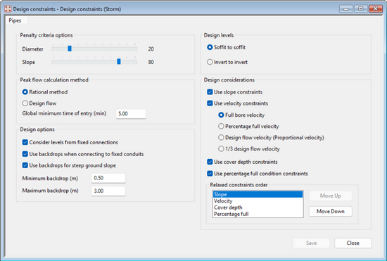
Design constraints window
Penalty criteria options
Penalty criteria control how feasible candidate pipes are ranked when multiple solutions satisfy all constraints.
Available criteria:
- Diameter
- Slope
These sliders define the relative importance of pipe size versus pipe slope when ranking feasible candidates.
Increasing the weighting for Diameter decreases the weighting for Slope, and vice versa.
If multiple candidates satisfy all constraints, the candidate with the lowest total penalty score is selected.
Penalty weightings are relative and influence ranking only among candidates that already satisfy feasibility conditions.
In order to compare the penalty scores for different pipe shapes, the hydraulic radius is used as a proxy for the pipe size instead of the diameter.
Peak flow calculation method
The Peak flow calculation method setting determines how design flows are calculated during the Network design process. These flows are used to establish the required capacity in each pipe to conform with the flow in each point of the network.
Two peak flow calculation methods are available.
Rational method
Peak flow is calculated using rainfall intensity derived from an IDF curve and the calculated time of concentration (Tc) in each point of the network considering the time of concentration in each subcatchment and the time of travel within the pipes.
Rainfall intensity is selected from the IDF curve using the calculated time of concentration and the return period specified when running Network design.
Downstream design flow
When using the Rational method, the design flow does not decrease as Network design progresses downstream. If the calculated flow at a downstream pipe is lower than the flow from the upstream pipe, Network design uses the upstream flow as the design flow for that pipe.
Pipes on branches that do not yet receive contributing flow may have a design flow of zero until they join a contributing upstream path.
Design flow
Design flow mode is intended for sanitary systems or situations where flows are known and could be specified directly by the user.
In this mode, rainfall data, subcatchment areas, and time of concentration are not used to calculate flows.
To calculate population based sanitary flows, users can utilize a design flow Ruby Script object that will trace the accumulation of population at each point of the network and multiply it by a peak flow factor and per-capita flow to establish the design flow and assign it to the relevant pipe. The Ruby Script object is available in the Sample Model attached to the 1D and 2D Network Tutorials and in the Autodesk Water Infrastructure Github.
Global minimum time of entry (min)
This parameter applies only when the Rational method is selected.
It defines a lower bound on the time of concentration used when selecting rainfall intensity from the IDF curve.
If the calculated Tc is smaller than this value, the global minimum time is used instead when selecting rainfall intensity.
The minimum time of entry affects rainfall intensity selection only at the subcatchment where it is applied. Downstream time of concentration values continue to accumulate from upstream Tc and pipe travel time.
For details on time of concentration calculation, see Time of concentration in the IDF curve topic.
Design options
The Design options settings control how Network design accounts for fixed connections and whether vertical drops (backdrops) may be introduced to maintain feasible pipe slopes.
Consider levels from fixed connections
When enabled, links outside the design region may provide fixed upstream, downstream, or side-branch connection levels.
The design tool will ensure that the network has hydraulic connectivity with the level of these fixed connections. These levels are treated as constraints during candidate evaluation and may restrict the feasible slope range for links within the design region.
Supported structures (pumps, orifices and weirs) within the designed run also provide invert levels that the design attempts to connect to.
When this option is disabled, levels from adjacent links outside the design region are not considered during slope feasibility calculations.
Use backdrops when connecting to fixed conduits
When enabled, Network design may introduce a downstream backdrop where required to save on excavation cost whilst maintaining connectivity with a fixed downstream link.
This may occur when the slope required to meet the downstream connection level exceeds the allowable slope range for a candidate pipe, or when satisfying the connectivity constraint would otherwise result in an infeasible slope.
In these cases, a downstream backdrop may be introduced to reduce the slope requirement while maintaining level connectivity with the fixed conduit.
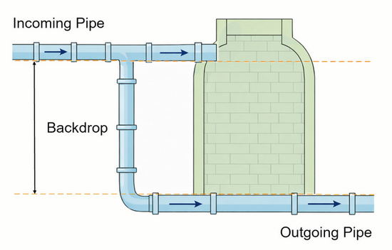
Backdrop illustration
Use backdrops for steep ground slope
When enabled, Network design may introduce an upstream backdrop where required to maintain the minimum cover depth in locations where the ground is steeper than the maximum allowable slope.
This may occur when the slope required to satisfy minimum cover depth exceeds the maximum allowable slope for a candidate pipe due to steep ground slope.
In these cases, an upstream backdrop may be introduced to reduce the slope required to satisfy the cover depth constraint.
|
Note: When the backdrop is introduced for steep ground, InfoWorks ICM will start from the minimum cover depth at the downstream end and then work out the upstream invert level based on the minimum slope out of the:
If the maximum pipe slope caused by the other constraints is higher than the maximum slope limit from the pipe catalog, then this would result in a failed design. The behaviour will be altered in the next release for the specific situation where the maximum pipe catalog slope limit is higher than the maximum slope caused by the other constraints. InfoWorks ICM will take the maximum of these two slopes rather than the minimum to save excavation costs. |
Minimum backdrop (m)
Defines the minimum allowable vertical drop applied when introducing a backdrop.
If a backdrop is required during candidate evaluation, the resulting drop must be greater than or equal to this value.
This setting represents a constructability threshold, as very small vertical drops may not be physically constructible.
Maximum backdrop (m)
Defines the maximum allowable vertical drop applied when introducing a backdrop.
If the drop required to restore feasibility exceeds this value, the candidate pipe remains infeasible.
This setting limits excessive vertical drops that may generate high velocities, turbulence, or non-compliance with local standards.
Backdrop behaviour
Backdrops may be introduced automatically where slope requirements derived from connectivity or burial depth would otherwise exceed the allowable slope range.
Two situations may lead to backdrop introduction:
- connecting to a fixed downstream conduit at a higher level
- maintaining the required minimum cover depth where ground slope would otherwise force the pipe to exceed allowable slope limits
Backdrops are considered during candidate feasibility evaluation and penalty ranking.
Backdrop application is recorded in the Design report.
Design levels
The Design levels setting determines how upstream and downstream pipes are connected during a pipe size change.
Two alignment modes are available. Soffit to soffit when the pipes soffit levels are aligned and invert to invert when the invert levels of the pipes are aligned.
Soffit-to-soffit alignment maintains crown continuity between pipes and can reduce the likelihood of local surcharge conditions. For this reason, soffit-to-soffit alignment is generally preferred where practicable.
Invert-to-invert alignment may be useful where downstream level constraints limit network depth. In this mode, resizing pipes does not deepen the network.
Note: when connecting to structures, soffit elevations are not available. In these cases, the soffit level is estimated using the invert level plus a height derived from the smallest pipe size in the selected Pipe network catalog.
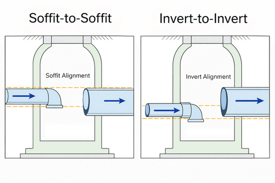
Design levels comparison
Design considerations
The Design considerations options control which constraint categories are applied when evaluating candidate pipes.
Each enabled constraint contributes to the lower and upper slope bounds used during pipe candidate evaluation.
A candidate pipe is considered feasible only if a slope exists within these bounds.
If the calculated slope of the candidate pipe exceeds the upper slope bound, the candidate pipe is rejected as infeasible.
These constraints affect only candidate evaluation and final slope selection. They do not affect:
- peak flow calculation
- rainfall intensity selection
- time of concentration
Use slope constraints
When enabled, minimum and maximum slope limits defined in the Pipe network catalog are applied.
Candidate slopes must fall within the catalog-defined slope range. These limits contribute to the slope bounds used during feasibility evaluation. The slope required to meet the minimum slope requirement is referred to in the Design report as S-Slope.
If disabled, catalog slope limits are not applied during candidate evaluation.
Use velocity constraints
Velocity constraints define how the Network design tool calculates velocity-based slope limits for each candidate pipe. For each option from the Pipe network catalog, the tool determines a feasible slope range from the enabled design constraints.
For velocity constraints, the selected calculation mode controls the assumed flow depth used to calculate the minimum slope required to satisfy the minimum velocity constraint and the maximum slope permitted by the maximum velocity constraint.
The required slope is calculated by inverting the applicable flow equation, using either Manning's or Colebrook-White according to the conduit friction setting. Each velocity mode evaluates the constraint under a different hydraulic condition, so the same pipe and catalog entry may produce different velocity-based slope values in the Design report.
| Full bore velocity |
Calculates the slope that satisfies the velocity associated with the full-bore conditions, where the pipe is assumed to be flowing full. The calculation uses the velocity associated with the full depth and the full hydraulic geometry of the candidate pipe. |
| Percentage full velocity |
Calculates the slope that satisfies the velocity using the depth defined by the configured percentage-full constraint within the Pipe network catalog. The calculation uses the velocity associated with the hydraulic area, wetted perimeter, and hydraulic radius corresponding to that partial-flow depth allowed in percentage full design limit. |
| Design flow velocity (Proportional velocity) |
Calculates the slope that satisfies the velocity using the flow depth expected at the calculated design flow. The design flow is used with the target velocity to determine a target flow area, which is then converted to a flow depth for the candidate pipe geometry. |
| 1/3 design flow velocity |
Calculates the slope that satisfies the velocity using one third of the calculated design flow. This follows the same approach as Design flow velocity, but with the flow factored by one third. Note: This mode can be a demanding constraint because the lower flow condition may require a steeper slope to satisfy the selected velocity limit. Some standards allow drainage designers to use a pre-defined fixed slope once the designer fails to meet this condition with a reasonable slope.
|
Use cover depth constraints
When enabled, minimum and maximum cover depth limits defined in the Pipe network catalog are applied.
Candidate slopes must allow pipe elevations that satisfy cover depth requirements.
Cover depth constraints contribute to slope bounds during feasibility evaluation. The slope required to achieve a downstream cover depth that is equal or higher than the minimum cover depth is referred to as D-slope in the report
Cover depth values must be greater than or equal to 0 and cannot exceed 1000 units.
If disabled, cover depth limits are not enforced during candidate evaluation.
Use percentage full condition constraints
When enabled, the maximum percentage full condition defined in the Pipe network catalog is applied during candidate evaluation.
Maximum percentage full is evaluated as a depth ratio (d/D).
The percentage full condition is considered when calculating the capacity available in each pipe candidate. The pipe capacity considering the allowable percentage full should be equal or higher than the design flow in order for the pipe candidate to be considered feasible.
Percentage full values must be greater than 0.
If disabled, all pipe candidates will be allowed to be running full.
Relaxed constraints
Use relaxed constraints to allow network design to continue when a pipe cannot be designed using the main constraint values. InfoWorks ICM first attempts to design each pipe using the standard slope, velocity, cover depth, and percentage full condition constraints. If the pipe cannot meet those constraints, InfoWorks ICM can retry the design using relaxed values for selected constraint types.
Relaxed constraints are applied locally. They do not replace the main constraints for the whole network. When a pipe requires relaxation, InfoWorks ICM applies the relaxed constraint types in the order shown in the Relaxed constraints order list. After that pipe is resolved, the design continues using the main constraints again.
The relaxed values are defined in the pipe network catalog. For each parameter, the relaxed value extends the permitted range used during fallback design. If you do not want a parameter to be relaxed, set its relaxed value to match the main constraint value.
Use Move Up and Move Down to control the order in which relaxed constraint types are tried:
| Slope |
Allows InfoWorks ICM to use relaxed minimum or maximum slope values where the preferred pipe gradient cannot be achieved. |
| Velocity |
Allows InfoWorks ICM to use relaxed velocity limits where the preferred velocity range cannot be achieved. |
| Cover depth |
Allows InfoWorks ICM to use relaxed cover depth limits where the preferred cover depth cannot be achieved. |
| Percentage full |
Allows InfoWorks ICM to use relaxed percentage full limits where the preferred design fullness cannot be achieved. |
InfoWorks ICM first tries to design the pipe with no relaxed constraints. If that fails, it tries the first relaxed constraint type in the list. If the design still fails, it continues down the list. Put the constraint type that is most acceptable to relax higher in the list, and put constraints that should only be relaxed as a last resort lower in the list.
Enable relaxation for individual pipes
By default, relaxed constraints are not applied to an individual pipe. To allow Network design to use relaxed constraint values for a specific pipe, select Enable relaxation in the pipe properties.
This lets you allow relaxation selectively, for example in parts of the network where greater design flexibility is acceptable, while keeping other pipes subject to the preferred constraint values.
Selecting Enable relaxation does not define the relaxed limits. Network design uses the relaxed values already defined in the Pipe network catalog for the enabled constraint types.