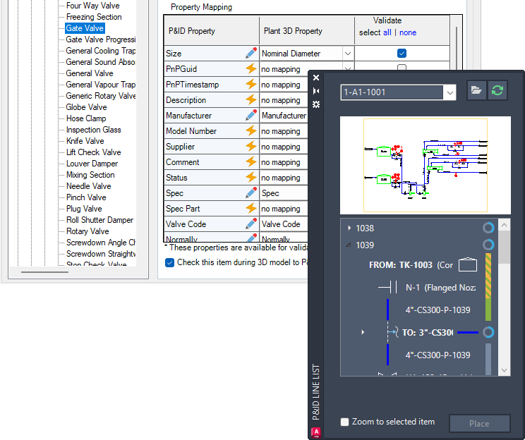
The P&ID Line List window provides a comprehensive view of the P&ID drawing, displaying all line segments and their associated components, such as inline components, nozzles, start/end equipment models, branches, and off-page connectors.
Using the line list, you can select any available P&ID object and place its corresponding Plant 3D counterpart in the 3D model. This ensures that the property values of the P&ID object are accurately copied to the 3D model.
- It is highly recommended to map a P&ID object to a Plant 3D object before placing an equivalent Plant 3D object in the model. When you place unmapped items, the Custom Parts dialog box is displayed.
- P&ID line segments are always mapped to Plant 3D pipes.
- For better performance of the P&ID Modeler preview, it is highly recommended to turn on the PLANTLINELISTUSEGSF system variable to enable the fast shaded mode.
Indicate Piping Completion Rate and Status
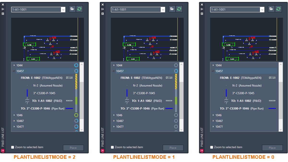
Indicators are displayed in the P&ID Modeler to help communicate overall completion rate and status.
A circle is displayed for each pipeline group and branch, representing the overall completion rate. Hovering over the circle displays the completion percentage for the pipeline.
A colored bar shows the completion status of each component:
- Green - The component is modeled, and all mapped properties match.
- Green and Yellow dashes - The component is modeled, but some mapped properties do not match between the P&ID and piping models. Hovering over the status bar displays a tooltip with details.
- Gray - The component is not modeled.