The following steps describe typical workflows for running wind tunnel analysis simulations.
To use the Wind Tunnel feature
- Open a model that contains conceptual massing elements.
- Specify the geographic location of the project. See Specifying the Project Location.
- Click Analyze tab
 Climate Analysis panel
 Wind Tunnel. Note: The 2D slice animation is run by default when you first open the Wind Tunnel feature.
 - (Optional) Modify default settings for data and model display. See Specifying Settings for Ecotect Wind Tunnel.
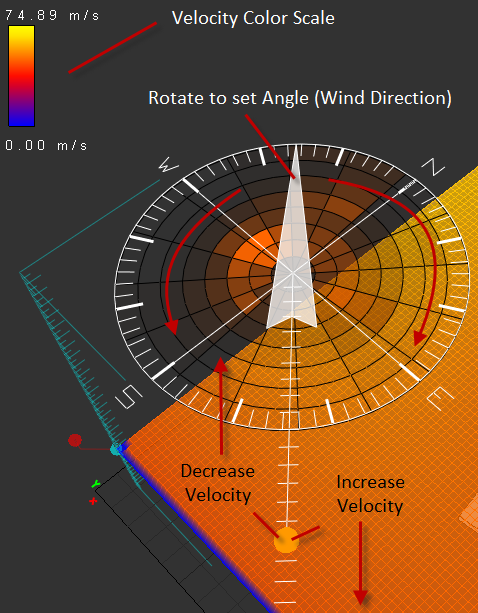
- Set the wind velocity. In the model view, select the compass as shown below and slide the gauge to increase/decrease the wind velocity. Or under Real-Time Analysis, for Velocity (m/s), use the slider to set the wind velocity.
- Set the wind direction. Rotate the compass arrow as shown below, or under Real-Time Analysis, for Angle, use the slider to set the direction.

- (Optional) Expand Model Display. Click Detailed Wind Analysis to open the Wind Rose Chart. Use data from the Autodesk climate server as input wind direction using the Wind Rose feature. Specify the date and time ranges for the analysis.
- Expand 2D Grid Slice and for Analysis, specify whether to perform a 2D or 3D analysis. Select Show 2D Data Slice to analyze the air around the specified 2D grid slice. To analyze the entire space as defined by the grid, select 3D.Note: The 3D analysis results will display after the calculations have run, which may take some time depending on your machine's specifications and the analysis' level of detail.
- Create a simulation using one of the following methods:
Simulate a quick view of what airflow across the site will look like
- In 2D Grid Slice, ensure that Show 2D Data Slice is enabled and set to 2D analysis.
- (Optional) Adjust the Position on the grid axis and the 3D axis.
Create a specific airflow to assess potential wind tunnels along key circulation paths
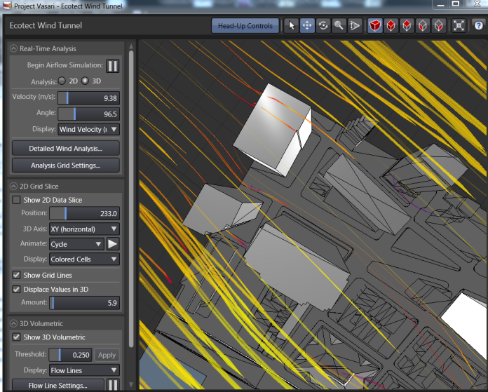
- Expand Real-Time Analysis. For Analysis, select 3D.
- Expand 2D Grid Slice. Select Show 2D Data Slice.
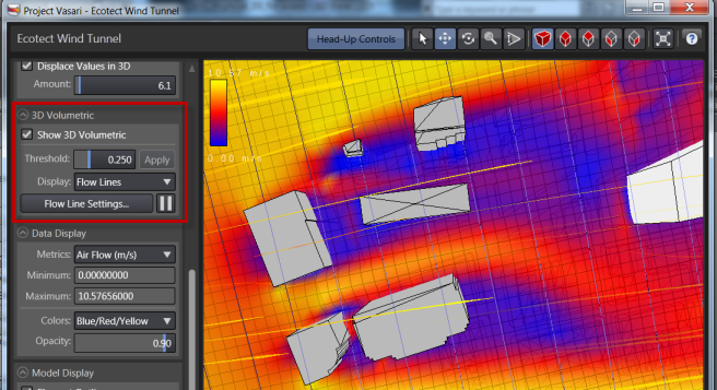
- Expand 3D Volumetric, and select Show 3D Volumetric.
- Adjust the view of the site so that you can see the air flow outside of the buildings and along pedestrian paths.

Create a simulation of how air flow moves around buildings
- In 2D Grid Slice, ensure that Show 2D Data Slice is unchecked
- Select 3D analysis.
- Expand 3D Volumetric.
- Select Show 3D Volumetric.
- For Display, select Flow Lines.

- Expand Real-Time Analysis and select Play/Pause to control the real-time airflow simulation.
- Adjust the wind velocity and angle as desired to run different calculations.
- (Optional) Adjust the settings for Data and Model Display as desired.
- To modify your model geometry based on the airflow simulation, close the Wind Tunnel feature. Edit your model(s) in the Conceptual Design Environment and then reopen the Wind Tunnel feature to iterate the analysis on your revised model geometry. Experiment with the calculations and your conceptual models to optimize potential air flow impact.