Adaptive points are modified reference points that are used when designing an adaptive pattern component.
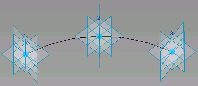
Adaptive points can be used for component placement (Placement Point) or as shape handles (Shape Handle Point). If the adaptive points are used for placement, they will be numbered in the order in which they will be placed when the component is loaded.
To create adaptive points
- Place free, hosted, or driving reference points where the adaptive point is needed.
- Select the reference point.
- Click Modify | Reference Points tab
 Adaptive Component panel
 Make Adaptive.
The point is now adaptive. To revert the point back to a reference point, select it and click ![]() Make Adaptive again.
Make Adaptive again.
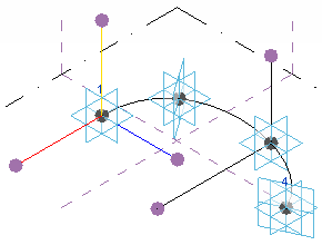
Notice that adaptive points are numbered in the order of their placement. Click the point number in the drawing area to change it. It will convert to an editable text box. If you enter a number that is currently being used as an adaptive point, the points will swap their numbers. You can also change adaptive point numbers on the Properties palette.
Geometry drawn using these adaptive points results in an adaptive component.
Adaptive Point Orientation
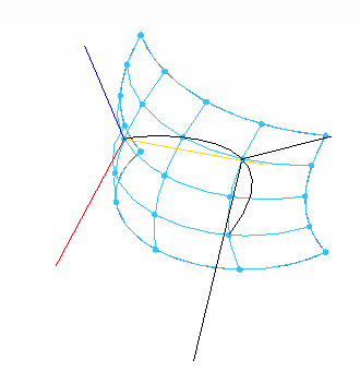
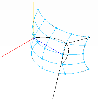
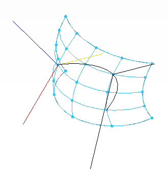
You can specify the vertical orientation of an adaptive point on the Properties palette. Under the Adaptive Component section, specify the Orientation property to one of the following. The examples shown are created with the following component family.
The yellow line represents top to bottom orientation; the red line represents front to back orientation; and the blue line represents left to right orientation. Note this orientation is in the adaptive component family. Notice how it changes when the orientation is set for the mass or component project environment.
By Host Reference. Perpendicularly orients from the host surface of the point.
Vertical on Placement. Vertically projects from the location of placement.
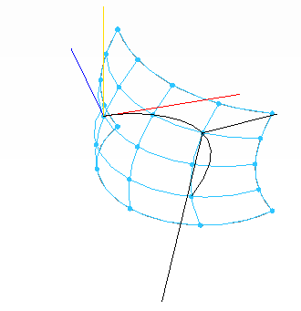
Auto-calculate. Generates optimal vertical projection for closed loop geometry.
Orthogonal on Placement. Vertically projects to the component or mass project environment. Orientation is from Top to Bottom, Front to Back, and Right to Left.
Vertical in Family. Vertically projects as placed in the component family.
Adaptive Shape Handle Points
You can use an adaptive point as a shape handle, meaning the point will not be used during placement but will be available to be moved after the component is placed. Select an adaptive point and on the Properties palette, select the Shape Handle Point (Adaptive) for the Adaptive Component Point.
Once the shape handle has been specified, you can constrain its movement. On the Properties palette, specify the Constrained property to None, Center (Left/Right), Center (Front/Back), or Ref. Level.