Use the Wind Tunnel feature to run computational fluid dynamics (CFD) simulations in order to analyze the potential impact of wind speed and direction on your project. The Wind Tunnel feature allows you to run either 2D or 3D airflow analyses using an interactive grid control and multiple options for displaying the analysis data and how it interacts with your model.
You can use the Wind Tunnel feature in conjunction with the Wind Rose feature to dynamically simulate the impact of wind speed, direction, and relative frequency for the location that you specified for your current project.
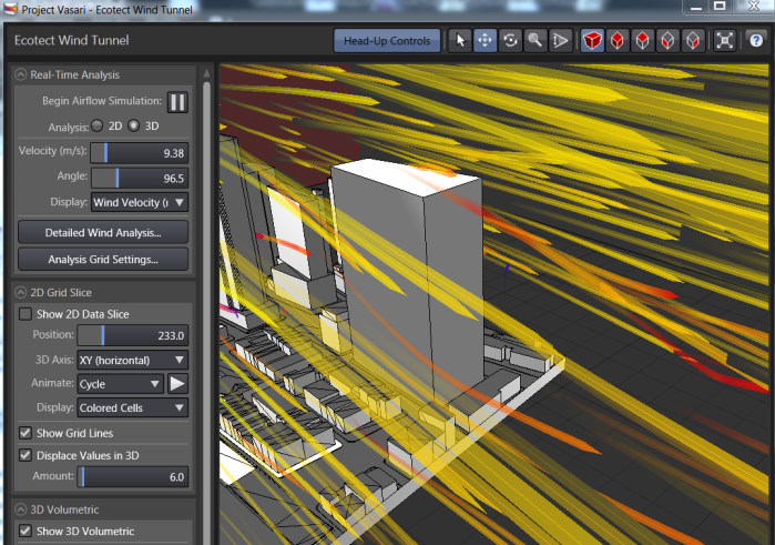
- Examine the impact of variations in wind and wake patterns on your site
- Simulate airflow around buildings to identify tunneling and canyoning effects
- Roughly estimate the impact of wind on pedestrian comfort and pressure distribution on structures
- Create specific snapshot views of how air flow may impact your site at specific times.
Examples of how this data can be used to influence your design decisions:
Before you begin using the Wind Tunnel feature, make sure that your model contains conceptual massing elements. Specify the Project Location and select a weather station. Then in the Wind Tunnel dialog, you can access the Wind Rose feature as shown below to specify a date and time range for the simulation. Then specify the wind flow analysis type, the size of the analysis grid, and set analysis data and model display settings. See Using Wind Tunnel.
You cannot change the geometry of your model in the Wind Tunnel view. If you want to iterate your design, close the Wind Tunnel and edit your model(s) in the Vasari conceptual design environment. Then reopen the Wind Tunnel feature, run an analysis on the current geometry and see how your design changes are affected by the wind flow calculations.
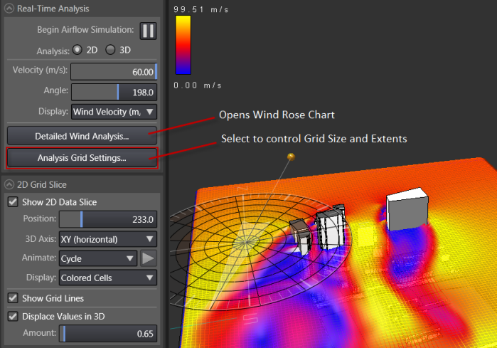
Considerations when setting the 3D Bounding Volume
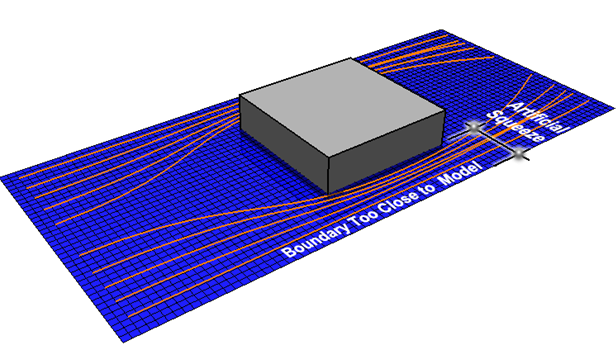
You may want to consider setting the horizontal extents 2 to 3 times the size of the model footprint.
Important: When setting analysis volume, leave sufficient space to allow for natural air flow around the model.
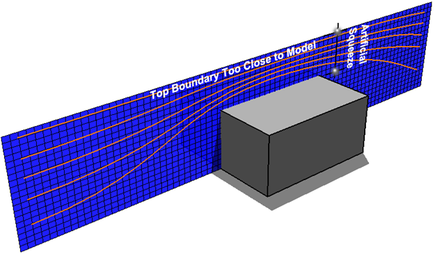
Important: Also leave space above to allow for natural air flow over the top of the model.
Considerations for 2D and 3D Analysis
The same issues must also be considered when choosing between a 2D and 3D analysis. In a 2D analysis, the entire air space is just a single flat plane. If the 2D plane is horizontal, air can never flow upward or downward in order to avoid obstructions, only around the sides as shown in the graphics below.
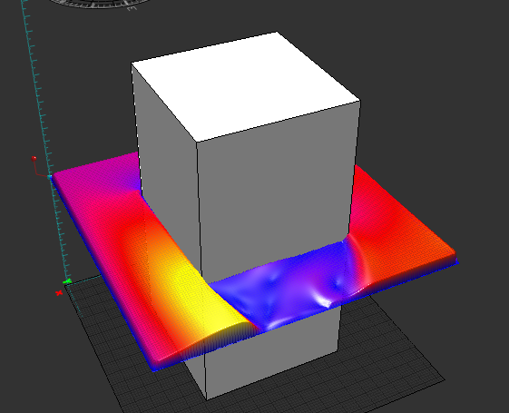
For a vertical plane, the same ideas apply, just the directions differ. This means that a 2D air flow analysis considers only those parts of the geometry that it actually intersects, and uses only air flow paths that exist within that 2D plane. If any geometry lies slightly outside that plane, both it and its potential turbulence effects are effectively ignored.
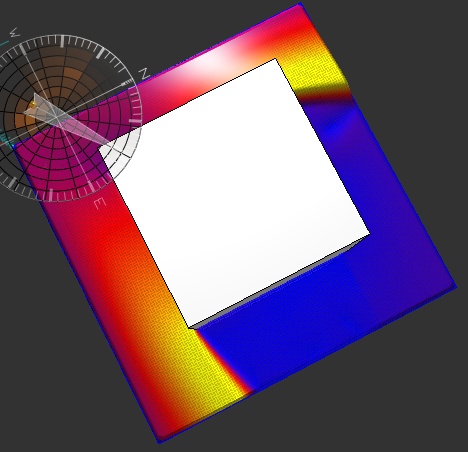
Now this does not mean that a 2D analysis is invalid or not meaningful. In fact, since they are much faster to calculate and animate, 2D analyses are potentially far more insightful than a full 3D analysis - provided that you account for their limitations in the way that you interpret the results. Also, the 3D analysis has similar limitations; a 3D analysis ignores all geometry that is not actually within its 3D volume and, as described above, it considers only air flow paths that exist within that volume.
All forms of CFD analysis, whether in this feature or in a dedicated CFD application, require interpretation for their results to be meaningfully applied. However, since they are highly visual and interactive, CFD tools such as this feature can actually help you to understand these limitations and their effects as you gain experience experimenting with different models under different conditions.
The wind tunnel is a fast, efficient method of exploring the impacts of wind on your site. Autodesk Simulation CFD is available for those interested in more detailed flow simulations, accounting for thermal effects, modeling combined interior/exterior flows, or studying contaminant or exhaust dispersion patterns.