The Display Settings form allows you to set the various view display and property settings. The tabs on the Display Settings form give you access to specific areas of the views available.
Toolbar
The toolbar gives you the following options:
Open File – Locate and open an *.iddsx file that contains pre-set values for the Display Settings tabs.
Save File – Save the current Display Settings tab values to an *.iddsx file.
Default colours – Set the display colours for all items listed on the form to a predefined list of colours.
Default Deluge colours – Set the Deluge display colours to a predefined colour set.
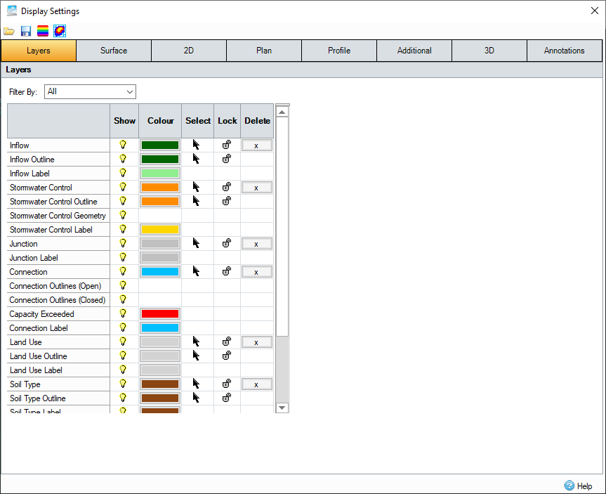
Layers Tab
This table dictates the visibility, display colour and object control of the listed layer items.
The layers can be filtered using the drop-down list above the table. This allows the table to be reduced to only show the layers required.
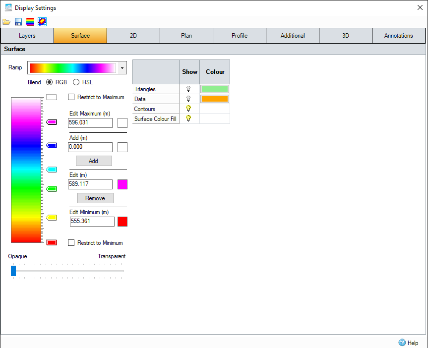
Surface Tab
The table dictates the visibility and colour of the listed layer items. The Colour Ramp dictates the colours of the Contours and Colour Fill that can be rendered for a given set of Surface Data.
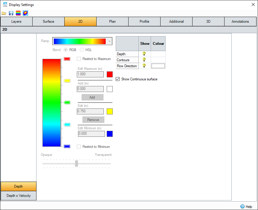
2D Tab
The table dictates the visibility of the listed layer items.
The Colour Ramp dictates the colours of the Depth that can be rendered after Deluge or 2D analysis for a given set of Surface Data.
The Deluge or 2D water surface can be drawn as a series of independent elements (as analysed) or as a continuous surface. When Show Continuous Surface is selected, the element level is applied at the centre of each mesh element and the level linearly interpolated in between.
Flow direction colour only applies to Deluge as 2D uses the Depth x Velocity colour band instead.
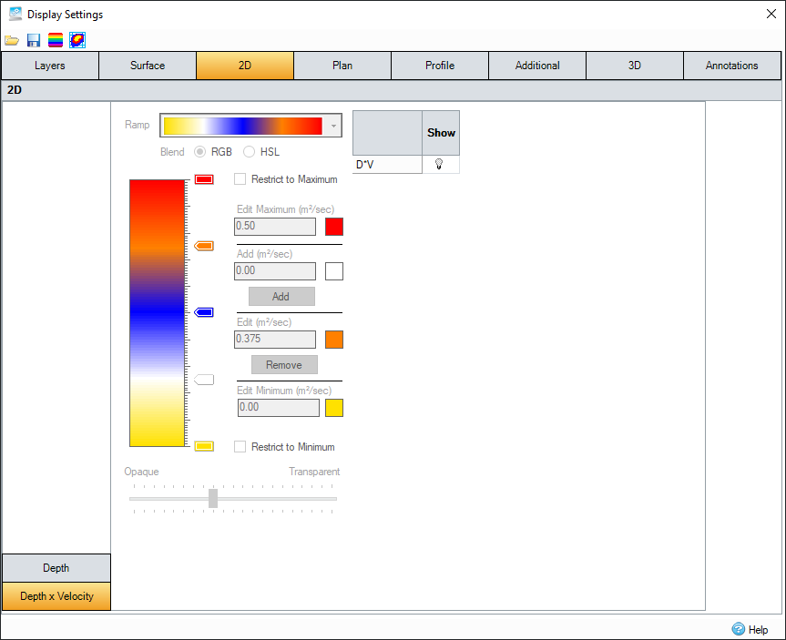
Depth x Velocity options
The Colour Ramp dictates the colours of the Depth x Velocity that can be rendered after 2D analysis for a given set of Surface Data.
Items in this tab are only editable after a 2D has been run and are not used for Deluge.
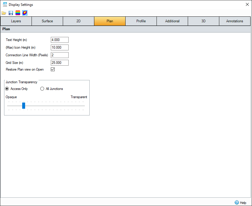
Plan Tab
The following fields are available in the Plan tab:
Text Height – Sets the text height on Plan.
Icon Height – Sets the maximum icon size when zooming on Plan.
Connection Line Width – Sets the line width used to render Connections (in pixels).
Grid Size – Sets the tick interval of the grid when shown on Plan.
Restore Plan view on Open – Sets the Plan to remember the view/zoom setting that was last used when re-opening.
Junction Transparency
Access Only or All Junctions – Decides what junctions are affected by the transparency slider.
- Access Only – Only affects junctions that require access.
- All Junctions – Affects all junctions on the plan.
Transparency Slider – Sets how transparent the objects appear on the Plan. The left-most side giving no transparency and the right-most side making them completely transparent.
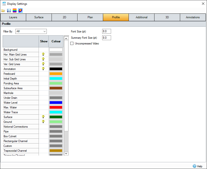
Profile Tab
The table dictates the colours of the items shown on profile view, both in the primary window and on the Plot Profile form.
The layers can be filtered using the drop-down list above the table. This allows the table to be reduced to only show the layers required. Layers can be turned on and off by clicking the light bulb icon in their row.
You can also modify the following fields:
Font Size – Sets the annotation and axis text font size on the Profile.
Summary Font Size – Sets the font size for the Summary table on the Profile.
Uncompressed Video – Select this option to turn off video compression for profile recordings.
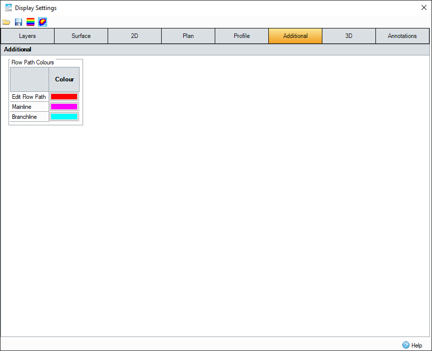
Additional Tab
The table dictates the display colours of the listed Flow Path items.
3D Tab
The following fields are available in the 3D tab:
Vertical Scale – Sets a scaling factor for the vertical axis in 3D. Available ratios are 1:1 (no scaling), 1:2 (vertical components twice as large as accurate values), 1:5, and 1:10.
Text Height – Sets the text height in 3D.
Icon Height – Sets the icon height in 3D.
Table – Specify colour, visibility, wireframe or filled, and use of colour ramps, where applicable, specific to 3D.

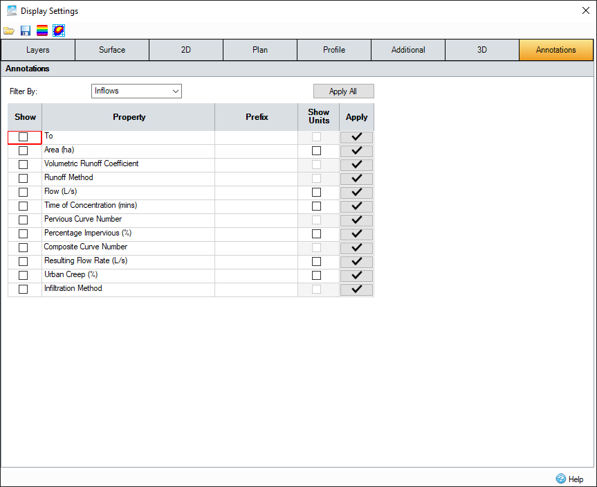
Annotations Tab
The table dictates the display of annotations for the different types of items on the Plan View.
The different types can be filtered using the drop-down list above the table. This displays the annotation properties that apply only to that specific type of item, with a secondary filter then provided for the more complicated Stormwater Controls.
The table allows the specification of the visibility (for new items), the prefix and whether the units should be displayed for the property. Note: Units can be displayed only on properties that have dimensions.
Constructing an annotation
The annotation shown on the Plan will use the settings from the Annotation tab, together with the selected properties for the specific item, to construct the annotation. Each item exposes its current annotations on the Properties box as the first column of tick boxes, which allows the annotation to be adjusted on a per item basis as needed. E.g. not all manholes need to show outlets. The Prefix and Show Units setting on this tab will be then used for each of the selected properties to construct the annotation with each appearing on a new line. E.g.
Prefix: VALUE (unit)
Length: 100.000m
New Items
New items that are added will automatically follow the current annotation settings for that item, so will annotate those set to 'Show' (where applicable).
Updating the selected annotations
If you wish to apply a change to the selected annotations for all items, this can be done using either the Apply All or Apply option for a row.
Apply All – Resets all of the data items in the phase to follow the currently selected annotations.
Apply button for a row – Applies this setting only to all instances of this data type in the current phase. E.g. Add Type to all Connections.
Align to Connections
Aligns the annotations to the angle of the connection. This is only available for connections.
Colour Ramp
The colour ramp shows the blended ramp used for Surface Level/Deluge rendering. If no pegs are defined, the blend is between the end peg colours. End peg values and colours can be adjusted as described below but they cannot be deleted. Moving the mouse over the ramp will display the level value at the mouse position. Pegs can be used to introduce a colour change in the blend. See Add and Remove below for peg editing. Right-click the Ramp to display a menu also described below.
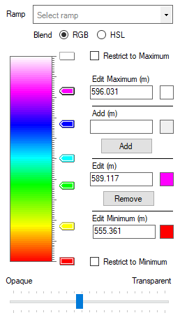
Ramp
The drop-down menu provides several default colour ramps. Any of the colour ramps can be used with either Surface or Deluge. However, some are more appropriate than the others.
Blend
When blending the ramp between pegs, the control can blend the RGB (Red, Green, Blue) settings for the peg colours or the HSL (Hue, Saturation, Luminance) settings. Although the blending results can be very similar, the difference is more pronounced when blending ‘opposite’ colours e.g.: Green and Magenta.
Restrict to Maximum
If this box is ticked, any value above the maximum value is not coloured on Plan.
If the box is un-ticked, the maximum colour is used for all values equal to or above the maximum.
Edit Maximum
This field is the maximum value of the colour ramp. When used for the Surface, this value is set to the Maximum Z value from the surface.
Changing the value and/or the colour will update the Max peg. This field can be set to a value larger if required, but helper test at the bottom of the form shows the absolute maximum value.
Add
Clicking the colour ramp will enter a value, appropriate to its position, in this field. The colour is set to the colour at the click position. Alternatively, you can enter a value and a colour. Clicking Add will add a new peg.
Edit
Clicking a peg will enter the peg details in this field. Changing the value and/or the colour will update the selected peg.
Remove
When a peg is selected, clicking Remove will delete the peg.
Edit Minimum
This field is the minimum value of the colour ramp. When used for the Surface, this value is set to the Minimum Z value from the surface.
Changing the value and/or the colour will update the Min peg. This field can be set to a smaller value if required, but helper test at the bottom of the form shows the absolute minimum value.
Restrict to Minimum
If this box is ticked, any value below the minimum value is not coloured on Plan.
If the box is un-ticked, the minimum colour is used for all values equal to or below the minimum.
Opaque – Transparent
Moving the slider sets the transparency of the colours on Plan. The transparency setting is not reflected on the ramp.
Right-click menu
The right-click menu on the Ramp provides some simple adjustment actions.

Even Space Pegs – Evenly distributes the pegs on the ramp.
Narrow Space Pegs – Distributes the pegs with a bias towards the minimum.
Invert Space Pegs – Reverses the peg distribution.
Invert Colour Ramp – Reverses the ramp colours settings.
Double Pegs – Doubles the number of pegs. Typically when viewing contours, this option will double the number of contours.
Delete Pegs – Deletes all the intermediate pegs but not the end peg Min and Max settings.