Quick start on process of building energy simulation using conceptual mass in Revit.
Energy Analysis for Autodesk® Revit® using conceptual masses is intended to provide insight into the role of building form (size, shape, orientation, glazing percentages, shading) and materials on building energy use from the earliest stages of the design process.
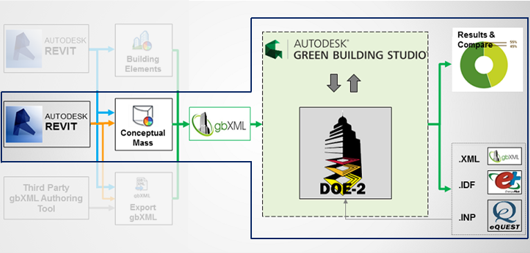
The following instructions describe how to perform an energy analysis using conceptual masses in Revit. Use these instructions to quickly create a baseline simulation that uses default energy settings. Then see the Energy Analysis using Conceptual Masses - Detailed Workflow to learn how to modify the conceptual mass model and its energy settings to refine the analysis.
|
|
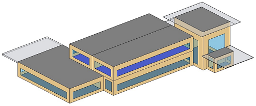
| Auto-zoning in Autodesk Vasari | Analytical spaces modeled in Revit |
If you’d like to download a model to use for the analysis, here is a Health Center model located in San Francisco.
|
Sign in to Autodesk 360
|
To use this feature, you must sign in to Autodesk 360. Click Sign in |
|
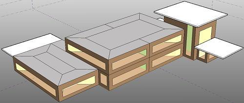
Create a mass model.
|
You can load a mass family into a project for simulation or create an in-place mass directly in a project. See Massing Studies. |
|
Add mass floors.
|
In the project environment, select the mass model, and add mass floors. |
|
Set Conceptual Masses as the basis of the Energy Analytical Model.
|
Click Analyze tab |
|
Create the energy model.
|
Click Analyze tab |
|
Define basic energy settings.
|
Click Analyze tab
For more information about these settings see Energy Settings. |
|
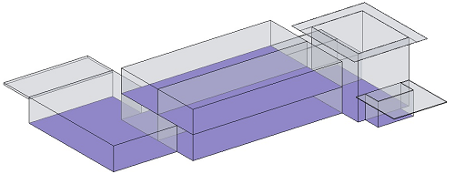
Run the Energy Simulation.
|
Display a 3D view of the model, and click Analyze tab |
|
Name the analysis and specify the Green Building Studio project.
|
In the Run Energy Simulation dialog, specify a name for the analysis, and select whether to create a new or use an existing Green Building Studio project. Then click Continue. (Choose a name that is descriptive of the model and energy settings, and ensure that the Project you’re assigning the run to has the proper location and building type settings.) |
|
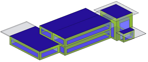
Simulated elements display.
|
The current view displays mass zones and mass shades, and it temporarily dims elements that are not included in the analysis. |
|
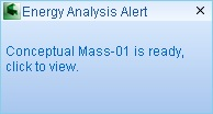
Access the results by clicking the pop-up alert or Results and Compare.
|
When the simulation is complete, an alert displays. Click the analysis name in the alert to view the simulation results. Or click Analyze tab |
|
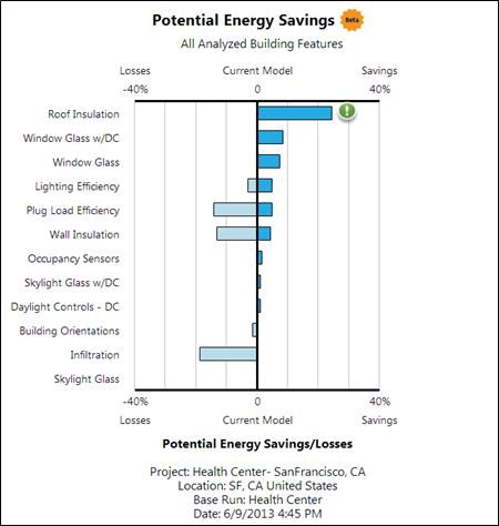
Review the simulation results.
|
In the Results and Compare dialog, view the analysis results. Tip: Use the Settings tab to select the charts to include in the results and to configure the display of energy analysis data on the Results tab. |
|
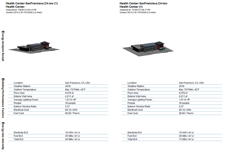
Make changes, simulate, and compare.
|
Modify mass model and energy settings as needed. Then repeat steps 5-9 to run a simulation on the modified model. For a side-by-side comparison of simulation results, select multiple analyses and click Compare on the toolbar. |
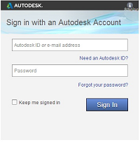
 Sign in to Autodesk 360. Enter your Autodesk ID and password.
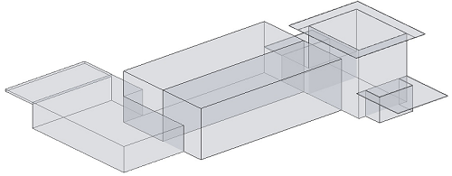
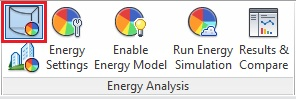
 Use Conceptual Mass Mode.
  Enable Energy Model.
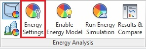
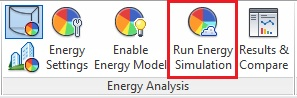
 Run Energy Simulation.
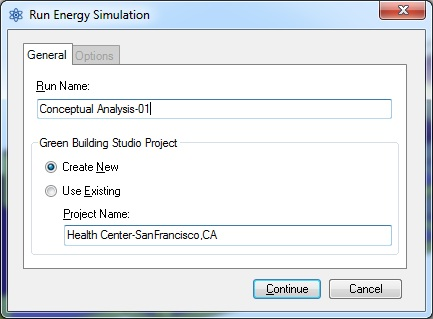
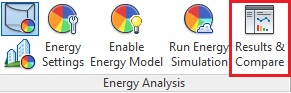
 Results & Compare, and select the analysis from the project tree.