Connector breakpoints are used for setting up the graphical qualities of a connector and the connector end Nodes. They have to be set up for each pattern library, i.e. Rectangular, Round, and Oval. The Database displayed in this help file is used in CAMduct and ESTmep. This is because these programs display all settings for Manufacturing, Costing, and Drawing.
- Open the Connector database by going to Fittings and selecting Connectors.
-
 The screen example below is the Connectors Manufacturing view which is the second icon along the top.
- This example is for Rectangular patterns.

- Double-click on a connector to display the connector settings.

- Click on the Breakpoints button to access the breakpoints dialog. Breakpoints allows the user to control how the connector is displayed in the drawing. On
Round and Oval
it can also be used to control the Connector End Node .
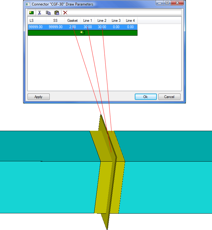
The fields available for setting the breakpoints are:
- LS / SS: These setting are used to define a series of breakpoints at which the connector will change settings. The green "New" icon can be used to add new entries to the breakpoints. These values work the same as the specification / pressure Class breakpoints and a detailed explanation of these settings can be found in the Specification section of this help. If the connector is not required to have more than one size / type then a value of 99999 is used to define a terminator value
- Gasket: Determines the gasket thickness for the Connector. This value physically separates two connected Items
- <Line 1>: Determines how far out the connector extends out from the duct
- <Line 2>: Determines how far the connector extends back into the duct. This value can also be used to simulate Slip Joints
- <Line 3>: This line is normally not used. However it can be used to raise the connector away from the duct body. This is useful when Shading or rendering to get proper separation between Duct and connector faces
- <Line 4>: This line is not used
Round and Oval Breakpoints are different in that they have more parameters. These are:
- Diameter: This is the Diameter of the tube that defines the Breakpoint.
- Extension: Defines the overall size of the Auto Extension, added to the end of the Item, to which the connector is attached. This should be at least equal to the Flange Thickness value
- Snap Offset: Defines the distance of the node from the end of the connector to allow for gaskets, sealant, weld prep, etc.
- Flange Extension: Defines how far the flange protrudes perpendicular to the body of the Item
- Flange Thickness: Defines the Thickness of the flange
- Flange Adjust: Allows the user to move the flange along the body of the Item
- Swage Set Back: Defines the location of the Node Snap point
- Swage Thickness: Defines the Thickness of the swage joint

The Table supports Swage, Flange, Coupling and Spigot-Socket type of connectors. The Extension Column defines the length taken up by the connection. When defining Product Dimensions, the Extension dimension can be set to Auto. In which case the values are picked up from the assigned connector. The Table above shows a typical multi size set up for Round Duct Swage Connectors
Changing Connector Drawing Options
To change Connector drawing options, Open the Database and select Connectors. Then click the
 Connector Drawing button. In the example below, the Connector Drawing view button is the fourth icon along the top.

This part of the connector Database controls how the Connector is displayed. Double-click on a connector within the Drawing view to display the option box below. This example is for a Rectangular pattern but the options listed below also cover Round/Oval patterns.
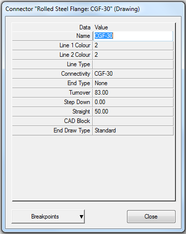
Line 1 Color / Line 2 Color: Controls the colors for the main two lines defining the connector. The basic colors available are based on AutoCAD colors and are as follows:
1= Red
2= Yellow
3= Green
4= Cyan
5= Blue
6= Magenta
7= Black
8= Dark Grey
9= Light Grey
0=White
There are other Gradient Colors that range from 10 to 249 which use a mixture of Tints and Hues, color Range 250 - 255 are shades of Grey.
Line Type: Sets the line type that connector will use for rectangular connectors.
Connectivity: The basic rule for interconnectivity is used with the End Type being Male >< Female. If the End Type is set to None we check this Connectivity field for the same Group Name. Beyond these rules, any connector can connect without a mis-match prompt, if the connectors Connectivity column has the same name.
End Type: Defines the rules for Connector Matching when two Items are joined together. End types are commonly used for the coupling logic by allowing for coupling items, that have the same connectivity group, to be automatically assigned between pipe / fitting connections. Each connector can be assigned an End Type which controls what it is allowed to connect to with out generating a warning; as per the following:
- Male: Will attach only to a Female connector in the same connectivity group. Else will report connector mismatch warning.
- Female: Will attach only to a male connector in the same connectivity group. Else will report connector mismatch warning.
- None: Will attach to any connector in the same connectivity group. Else will report connector mismatch warning.
Turnover: This option can be used to control additional material added or removed onto the duct for Manufacturing purposes.
Straight: This option allows the user to add additional straight to an Item to allow for connectors.
CAD Block: If a block exists in the drawing with the name of the Block entered here + "-???" where ??? is the duct size, it will draw that block at the duct end associated with the connector. An Example of this is found in the Victaulic connectors shipped with the program.
End Draw Type:
Standard: This is the default end type for the connector, this will have the nodes for attaching another fitting to that connector end.
Blank: This will put a Blank end on the Connector End so that the Attacher arrow will no longer attach to this end.
Step Down: This is used in Lined and Double wall ductwork and will step down to the Internal dimension for the next fitting. See Step Down Connectors.
Filter Out non user Data
 : This enables the user to exclude any Non User data from the Database. This is useful, for example, if you are working with Round Duct and you do not want to display all the Pipework Connectors that are supplied by the Manufacturer in their services.
