Leads are the pre-part and post-part cuts that ensure a smooth cut with no discernible start or end point. Lead styles are used when defining a part's cutting requirements in Profiler. The leads section allows for the editing of lead styles. Lead-in and lead-out lengths and types can be set for all types of islands. To access and amend these details Click on File
 Setup
Database
Manufacturing and select the Leads section or select the Database icon from the Utility Bar.
Setup
Database
Manufacturing and select the Leads section or select the Database icon from the Utility Bar.

Lead Style: This allows for different styles to be created, you can give the style a descriptive name in this box. To create a new style click on the
 icon. Each style is composed of the elements below.
Outer Lead / Hole Lead / Central: The leads defined are given both a length in millimeters and a type.
- An outer lead is a lead where the torch kerf (width) is offset to the outside of the part so that metal on the inner side of the cut comes out the correct size. An example of an outer lead would be around the outside of apart.
- A hole lead (or inner lead) is the opposite of an outer. The torch kerf is offset to the inside of the hole so that the hole is cut to the correct size. An example of a hole lead would be an access door.
- A central cut is where the kerf is equally distributed to both sides of the cut. Therefore the equality of the part sizes on both sides of the cut is preserved. An example of a central cut would be found between the segments on a segment bend cut from one part.

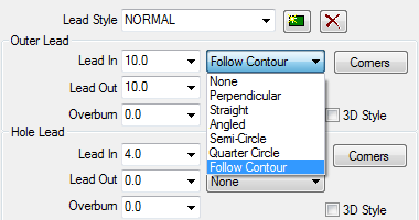
Each lead in / out can be defined as a particular lead type or as a created custom lead. Lead In is the length of cut that is made before the development is started. This can be set as a value or set to Auto.
If Auto is used then the Lead length is taken from the value specified in the Installed Machines
Tools Settings. This allows the user to create Material Specific Lead sizes.

Lead Out is the length of cut that is made after the development is completed. Overburn is the distance that the path of the cutter goes back over itself. Below are some examples of the lead types available. Leads are shown in red. Islands are shown in black. This value can also be set to Auto and the parameter set in the Installed Machines
Tools Settings.
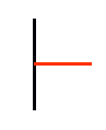
Perpendicular: A lead that intercepts the part at ninety degrees.
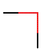
Straight: A lead that intercepts the part, usually on a corner, with no deflection angle - in other words it continues straight on to meet the part.

Angled: A lead that intercepts the island at a specific angle.

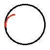
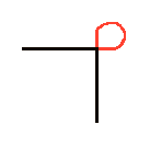
Semi-Circle: A lead that intercepts the island after first traversing a half circle of a defined radius.

Quarter Circle: A lead that intercepts the island after first traversing a quarter circle of a defined radius.
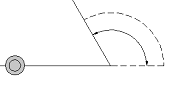
Follow Contour: This lead was developed for use with Router Cutting Systems.
Custom: A user-defined lead that is created in the Custom Leads section.
Corners: The corner style is for when the part demands a particular method of handling corners.

There are three alternatives to simply cutting the corners, 'as is'. Each alternative is shown below as applied to a ninety-degree corner where the torch will change direction from travelling left to right and move from top to bottom.
Stop and Start: This method means that the cutting torch turns itself off upon reaching a corner, and then back on again when cutting the next straight line. A new lead in / lead out will be generated every time a corner is reached if the corner angle is greater than the minimum angle.

Triangular: This method will attempt to give a sharp corner cut by keeping the torch turned on through a triangular shaped section for each corner, above the set minimum angle, in the part.

Clover Leaf: This method gives a sharp corner by keeping the torch turned on through a circular section for each corner, above the set minimum angle, in the part.
Size: Determines the size of the corner style extensions.
Min. Angle: Determines the minimum angle at which the corner style will be applied. The value entered defines the angle of change that the torch must make to go round the corner. In the diagram, the torch is travelling from left to right along the bottom and then alters direction to travel upwards from right to left, with the angle of change depicted by the arc.