Once tools have been added to a machine, the next step is to configure those tools with appropriate behaviors. There may also be times when you need to configure tools on a machine that is already setup. The procedure below describes how to configure tools on machines using the Machine Configuration dialog.
 ), no tools are installed to that machine by default. However, any tool listed in the [Tool Names] section (C:\Program Files\Autodesk\Fabrication <version>\CAMduct\toolbase.txt) can be added to the machine. When a tool is added to a custom NC machine, no Tool Globals, Details or Conditions are added by default, but any tool item listed in the [Tool Items] section of toolbase.txt, can be added. This contrasts with the externally hard-coded posts (which reply on an installed, externally hard-coded .VPL file) where all supported tools are added when a new machine (
 ) is created, and all supported Globals, Details, and Conditions are added when a tool is added.
 To configure tools on a machine:
- On the Edit Tools for Machine [Machine Name] dialog, in the left pane, select the tool to configure.
- Click Configuration to display the Machine Configuration dialog.
The Machine Configuration dialog lets you create or edit the controls codes (NC codes) for controlling general machine behaviors, as well as tool-specific behaviors, on a specified installed machine. For example, this dialog lets you create\write NC code for controlling general machine behaviors, such as motion, feed rate, arc centerlines, kerf, and more. This dialog also lets you configure tool-specific behaviors for the tool types that are included on the selected machine.
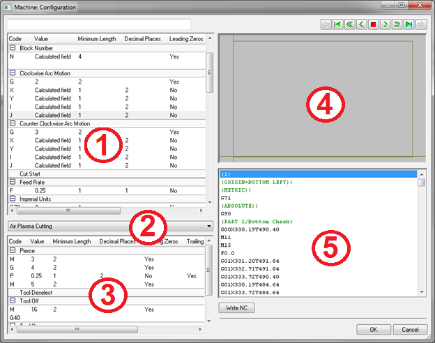 The following table describes the parts of this dialog that are numbered in the illustration above.
This area on the dialog Description 1 The top left pane of this dialog contains settings that let you specify the NC code for controlling general machine behaviors, such as:- Arc Centers: Absolute, Relative
- Motion: Absolute, Relative, Arc, Linear, Clockwise, Counter Clockwise
- Feed Rate
- Units
- Kerf
- Offset Origin
- Program Start\End
- Rapid Traverse
- Subroutines
- Block Numbers
- Cut Start
- Part Start
- Remarks
2 Click this tool selection drop-down list to display and select each of the tools that are included with this machine. Only the tools that have been added to the selected machine are displayed in this list. To add tools to the selected machine, see Add Tools to a Machine. 3 The bottom left pane of this dialog contains settings that let you specify NC code for the following tool-specific behaviors for each of the tool types that are included on the currently selected machine:
-
Pierce
-
Tool Deselect
-
Tool Off
-
Tool On
-
Tool Select
4 The top right pane of this dialog displays an NC view of the nested sheets for the current job. The buttons located along the top of this pane provide a variety of options for stepping through the machine motion. For example, you can Go To Previous Sheet/Next Sheet, Start\End, Backwards, Forwards.
The buttons located along the top of this pane provide a variety of options for stepping through the machine motion. For example, you can Go To Start\End, Backwards, Forwards.

5 Click the
 button to write or update the NC code specified. The code or updated code is displayed in this bottom right pane when this button is clicked.
 - To ensure that all fields and buttons are visible, begin by expanding the Machine Configuration dialog. Click the Maximize button in the upper right corner of the dialog, or manually resize the dialog.
- In the left pane, expand a behavior. For example, click "Absolute Arc Centers" to expand it.
- Use the right-click menu (right-click on an existing behavior) to perform the following tasks:
Right-click Menu Tasks 
- Edit: Edit an existing behavior by double-clicking it, or right-click
 Edit, to display the Edit Selected Field: Value dialog.
  This dialog lets you edit the following parameters:
- Code: Specifies the code.
- Value: Specifies the value.
- Minimum Length: Specifies the minimum length.
- Decimal Places: Specifies the number of decimal places.
- Leading Zeroes: Specifies whether or not to include leading zeroes.
- Trailing Zeros: Specifies whether or not to include trailing zeroes.
- Trailing Point: Specifies whether or not to include a trailing point.
- Parameter: Specifies the parameter.
- Change Type: Specifies whether the data associated with the type is a floating point value, integer, text or none.
- Change Context : Specifies which group of the internally calculated data can be used; for example, General (the machine setup parameter values in Globals, Details and Conditions), Sheet Properties, Motion, Cut, Parts, or Subroutines.
- Add: Add a new line of code by right-clicking Add.
- Delete: Delete any lines of code that are not needed.
- Move Up\Down: Move the selected line of code up or down.
- Change Group: Allows you to change the group.
- Edit: Edit an existing behavior by double-clicking it, or right-click
- Click OK to save any changes made using the Edit Selected Field dialog.
- Use the tool selection drop-down list to select each of the tools that are associated with the selected machine, and configure, add, or edit the code, using the bottom left pane of this dialog. Do this as necessary for each tool type included with the selected machine. Note that only the tools that were added for the selected machine are displayed on this drop-down list.
- When you are finished configuring all of the general machine behavior, as well as the tool-specific behavior for this machine, click the to create or update the NC code for this machine.
- Click the OK button located in the lower right area on the Machine Configuration dialog.