Design Line terminals, once applied to the active Design Line, can be altered. Using the Node  Terminals option from the Design Line menu, all the properties of the terminals can accessed.
Terminals when created typically need to be configured. Common tasks would be to specify the terminal flow or to enter the grill box size for terminals if using Size Entry.

The following properties can be accessed for terminals from this dialog:
- Button Code: The button code of the terminal placed onto the active Design Line.
- Flow (cu m/sec): The output flow value of the terminal in cubic meters per second. This can be accessed by right-clicking
 Flow and a preference can be made for the output flow of the terminal by selecting User preference. When using Design Line Constraint entry, based on the min/max velocity of each line, Design Line automatically calculates the size of the duct required based on the terminal output.
 - Elevation: The current elevation the terminal is placed at.
- Diameter: The size of the line feeding into the terminal.
- End Direction: For use with Side Entry terminals only. Set the terminal to position the spigot around each of the vertical axis points.
- Position: XY Coordinate of the terminal in the model.
- Size: The rectangular size of the line feeding into the terminal.
- Item Number: Right-clicking and selecting Renumber allows entry of a start number to assign to multiple terminals in the list.
- Carry Width and Depth: The dimensions of the terminal can be altered from the entry line size. Right-clicking on the terminal from within this dialog and selecting Edit Dims from Right Click menu allows for selection of new size. Re-calculating and Fill with then adapt the terminal to its new size.
- Worst Case Calcs: Used to combine/isolate the flow calculations of multiple terminals. For example, sprinkler terminals can be totalled together to give a combined flow. The default is to include and increases the line size based on the quantity of terminals included.
- Constraint Description: Constraint name of the line the terminal is connected to.
- Style: Terminal style name used for each terminal is displayed in this field. This defaults to the terminal style currently set on the button when placed into the Design Line. Right clicking and selecting Terminal Styles allows alternative styles to be applied. Re-filling applies the new style to that terminal.
Terminals Right Click Menu

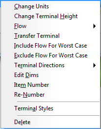
The right-click menu for terminals contains the following options:
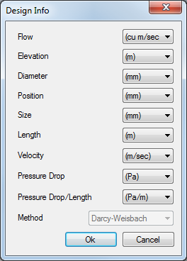
- Change Units: Allows alternative units to be used by default when displaying and entering the terminal Design Object Sizing dialog settings.

- Change Terminal Height: Changes the elevation of the terminal(s) selected. You are able to multiple select.
- Flow: This should be used if using Line Constraint entry for the duct Design Line so it can calculated on its size automatically based on this output flow value entered.
- Transfer Terminal: Flows can transfer to other terminals. Carries the flow from one Design Line to another to create the transfer.
- Include / Exclude Worst Case Calcs: Used to combine/isolate the flow calculations of multiple terminals. For example, sprinkler terminals can be totalled together to give a combine flow. The default is to include and will increase the line size based on the quantity of terminals included.
- Terminal Directions: For use with Side Entry terminals only, set the terminal to position the spigot around each of the vertical axis points.
- Edit Dims: The dimensions of the terminal can be altered from the entry line size. Right clicking on the terminal from within this dialog and selecting Edit Dims from Right Click menu allows for selection of new size. Re-calculating and Fill with then adapt the terminal to its new size.
- Item Number: Allows entry of the individual Item number.
- Renumber: Renumber allows entry of a start number to assign to multiple terminals in the list
- Terminal Styles: Terminal style name used for each terminal is displayed in this field. Defaults to the terminal style currently set on the button when placed into the Design Line. Right Clicking and selecting Terminal Styles allows alternative styles to be applied. Re-filling will apply the new style to that terminal. Multiple selection can be used to assign the same style to multiple terminals.
- Delete: Deletes the selected terminal(s). This also removes from the model when removed from this dialog.