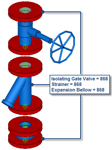
The following steps describe how to create a Valve Set sub assembly in CADmep by combining the following three items:
- Isolating Gate Valve
- Strainer
- Expansion Bellow
The following example shows a generic Valve item combined with a Strainer item, and an Expansion Bellow item.
- Insert these 3 items into the model, select within the active Service Template or folder structure, then position each item individually within the model as appropriate.
- With the items present in the model, consider the position and orientation of the items in relation to each other, as you would expect when utilising for coordination.
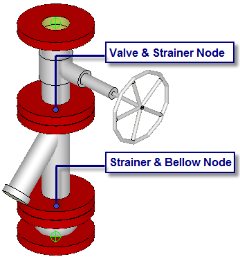
Each individual item has a distinctive node insertion point location, as shown below.
- With the items positioned in the correct location and orientation in relation to each other, type the SAVEASSUBASSEMBLY command, and then select the following 3 items: Valve, Strainer, Bellow.
- When you have finished selecting the items to be included in this sub assembly, press Enter to end the command.
The Save As dialog displays.
- Name and save this new sub assembly to an appropriate location within the folder structure, and click Save.
For this example, name this sub assembly Valve Set.
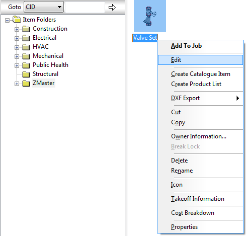
- To edit and customise, type FOLDERS, then locate the appropriate sub assembly previously saved.
- Right-click on this new sub assembly and select Edit.
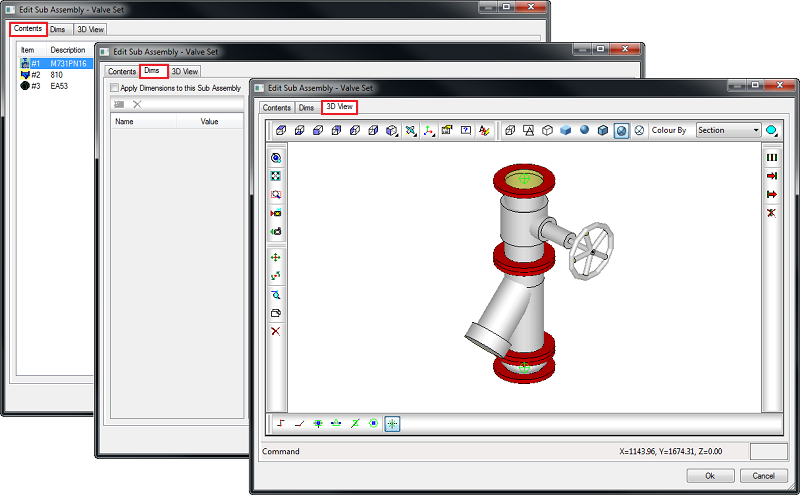
The Edit Sub Assembly dialog displays.
For more information, see Edit Sub Assembly Dialog.
The next step is to define the dimensions that will allow you to create the combined items within the sub assembly as a dynamically-sized individual item.
- Click the Dims tab, then select the Apply Dimensions to this Sub Assembly option, as shown below.
 Note: Prior to setting up the critical dimensions, plan and determine the dynamics required to create the sub assembly.
The next steps allow you to dynamically specify using a common diameter for Item #1 (Valve), Item #2 (Strainer) and Item#3 (Bellow).
- Select the New Dimension command. The column below titled Name, will populate a "Dim#1" title.
- Name this new dimension as required, for example "Connection Dia", then enter a value of 50.0 within the value column.
- To link the dimensions for Diameter #1 (Dim 0) for Item #1, Item #2, and Item #3 by selecting each field.
This indicates the three items within the sub assembly are now being driven by one common dimension for "Diameter #1 (Dim 0) titled "Connection Dia".

- Select OK to finalize and save the configured information to the sub assembly.
The next step is to define the insertion point. See Specify Insertion Point for more information.